Time division multiplexed optical measuring system

a multiplexed optical and time division technology, applied in the direction of electrical testing, measurement devices, instruments, etc., can solve the problems of difficult implementation of arrangement and various limitations and restrictions, and achieve the effect of reducing the number of optical fiber links and the number of electronics boards

Inactive Publication Date: 2006-03-07
ALSTOM TECH LTD
View PDF16 Cites 12 Cited by
  • Summary
  • Abstract
  • Description
  • Claims
  • Application Information

AI Technical Summary

Benefits of technology

[0015]An object of the present invention is to provide a voltage measuring system and method for measuring power line voltage employing optical electric field sensors with a minimal number of dedicated electronic circuits and / or circuit cards, and reducing the number of optical fiber links and number of electronics boards, while keeping the basic architecture of using multiple appropriately combined (e.g., weighted) optical electric field sensors to estimate power line voltage.

Problems solved by technology

This arrangement has been mentioned in the aforerecited U.S. Pat. Nos. 6,252,388 and 6,380,725, however, such an arrangement is difficult to implement and has various limitation and restrictions.

Method used


Image

  • Time division multiplexed optical measuring system
  • Time division multiplexed optical measuring system
  • Time division multiplexed optical measuring system

Examples


Embodiment Construction

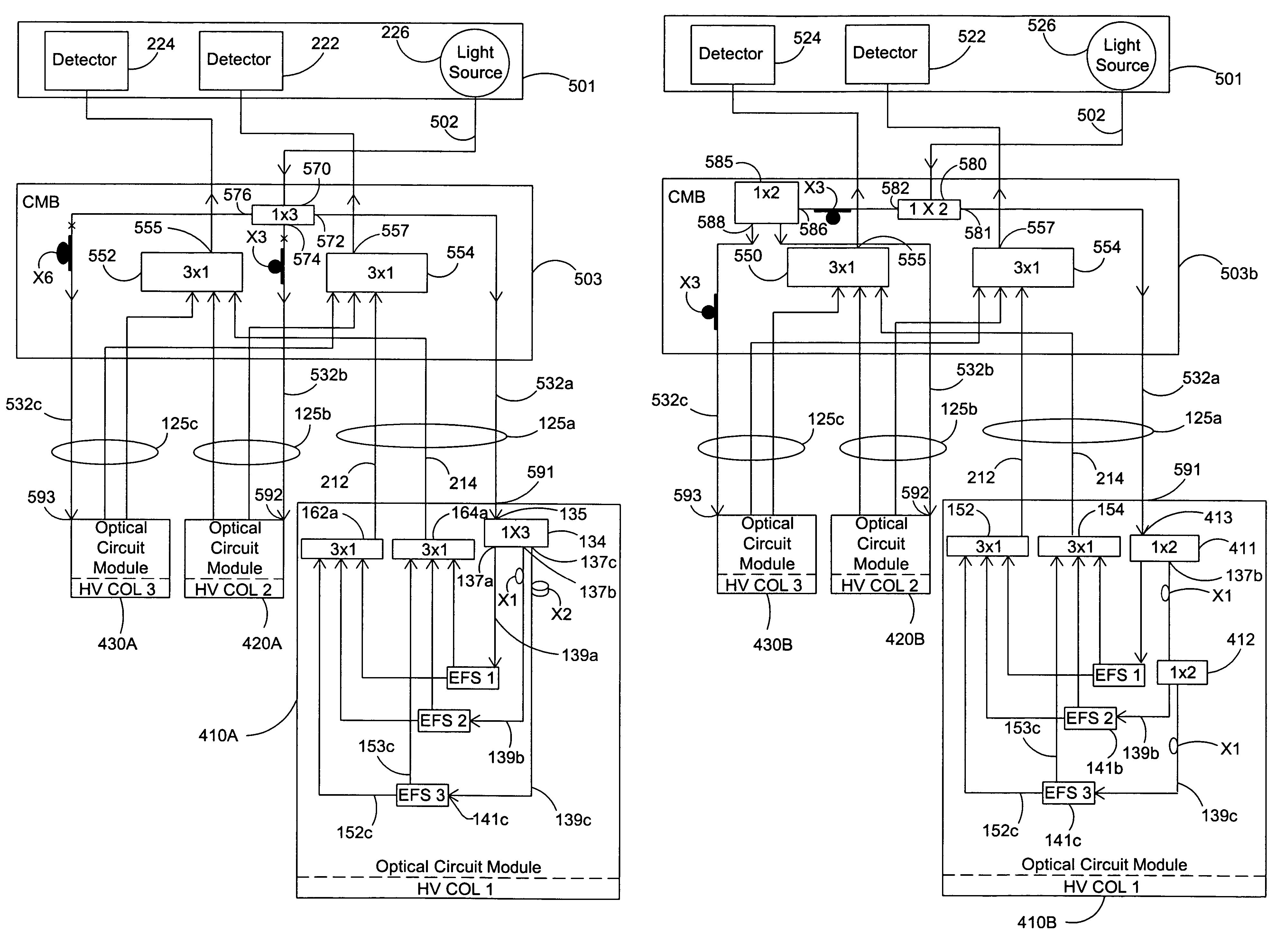
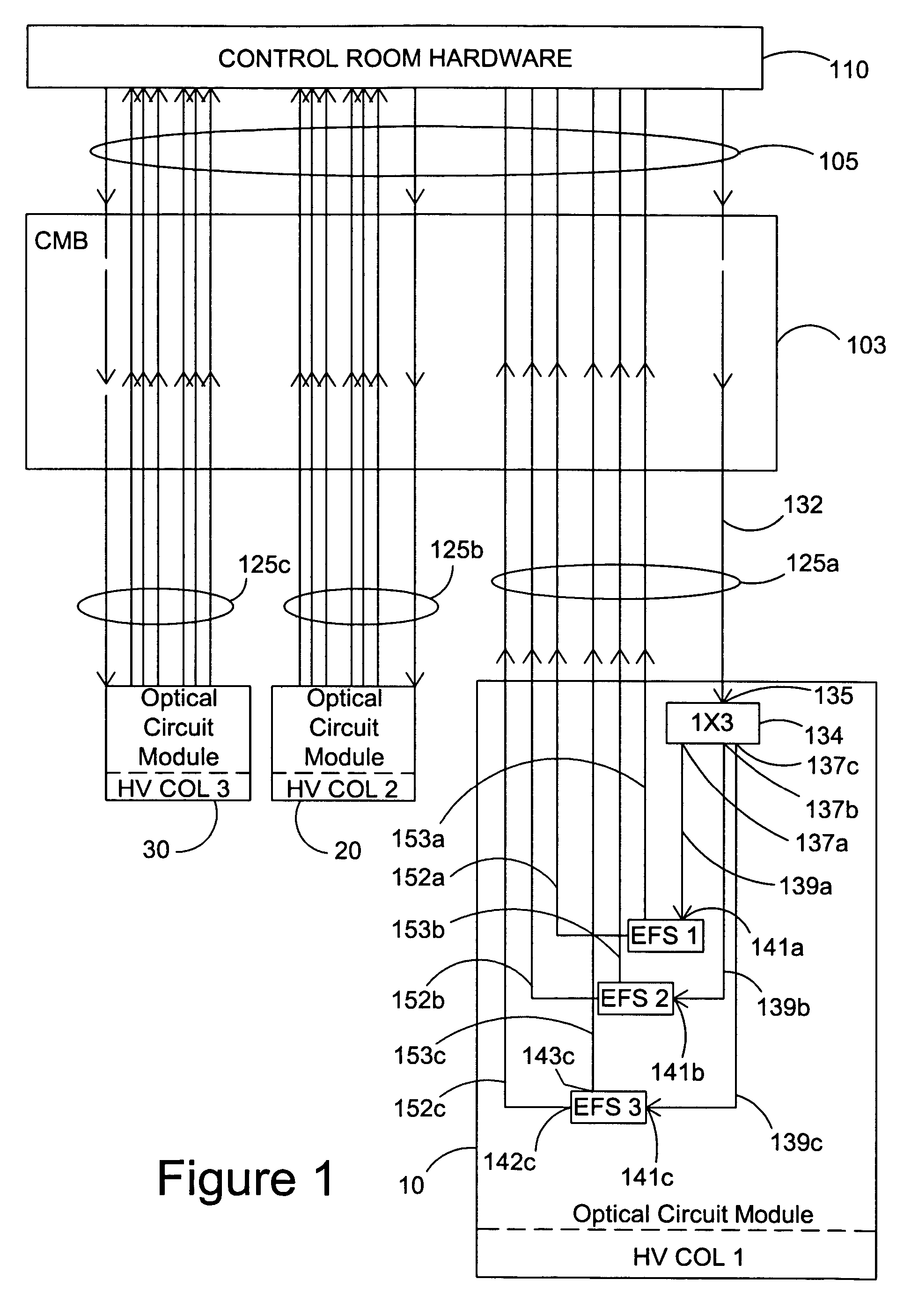
[0029]Illustrated in FIG. 1 is a simplified schematic block diagram of a voltage sensing system for a three-phase power line system of a complex optical and electronic system in accordance with one aspect of the present invention. In conventional systems, a high voltage insulator column is associated with each transmission line of a three-phase power system. Further, associated with each insulator column is an individual voltage sensing system for sensing the voltage of the particular transmission line coupled to the insulator column. As illustrated in FIG. 1, three identical individual high voltage columns are designated HV Col 1, HV Col 2, and HV Col 3 having corresponding high voltage sensing systems or voltage sensors 10, 20 and 30 respectively.

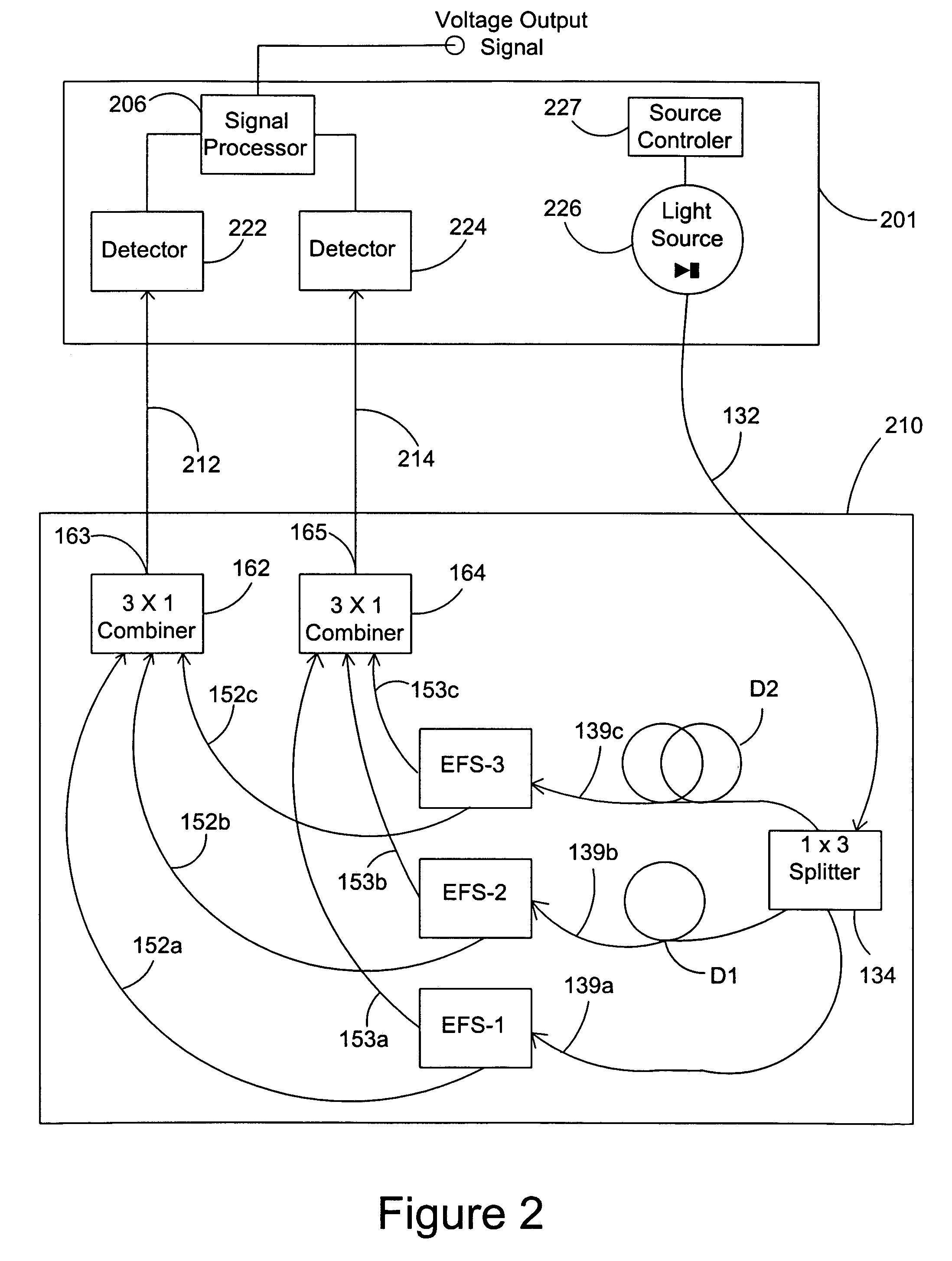
[0030]The present invention is particularly applicable to optical high voltage sensing systems or sensors where each voltage sensing system associated with each individual high voltage insulator column employs a plurality of optical elect...


PUM


Abstract

A time division multiplexed optical voltage measuring system includes an optical voltage sensing system module including, (i) a plurality of optical sensors where each sensor is responsive to an input interrogation light wave, and (ii) one or more optical outputs affected by sensed electric field thereat. The optical voltage sensing system module includes an optical circuit arrangement having (i) an input for receiving a module specific pulsed light wave derived from a primary pulsed light wave from a remote light source, and (ii) arranged such that each of the plurality of optical sensors receives an interrogation pulsed light wave. The optical circuit arrangement of the optical voltage sensing system module further includes at least one optical wave combiner for combining like-kind of outputs from all of the plurality of optical sensors. The optical circuit is arranged such that the pulsed light waves from the outputs of different optical sensors arrive at the optical wave combiner at differing times. In turn, the output of the combiner is passed to a detector and signal processor at a remote location for signal processing, and providing a measurement of the voltage intended to be measured. In a specific embodiment, each voltage sensing modules is arranged integral with a high voltage insulator column of a multi-phase power line system.

Description

RELATED APPLICATION[0001]This application claims the benefit of priority pursuant to 35 USC 119 of provisional patent application Ser. No. 60 / 500,665, filed 5 Sep. 2003, the disclosure of which application is hereby incorporated in its entirety by reference herein.FIELD OF THE INVENTION[0002]The present invention relates generally to voltage measuring systems and methods. More specifically, the present invention is related to a method and system for measuring voltage or current of a high voltage power line employing the use of multiple optical sensors, particularly optical voltage or electric field sensors, and optical current sensors.BACKGROUND OF THE INVENTION[0003]Voltage sensors for high voltage power line systems may be realized by the use of one or more electric field sensors. Further, such electric field sensors may be optical electric field sensors. The advantages of employment of optical sensors in power line applications are well known. Specifically a very significant adva...

Claims


Application Information

Patent Timeline
Patent Type & Authority Patents(United States)
IPC IPC(8): G01R31/00G01R15/24
CPCG01D5/268H04Q9/00G01R15/247
Inventor BLAKE, JAME N.RAHMATIAN, FARNOOSHROSE, ALLEN H.
Owner ALSTOM TECH LTD
Why Eureka
Try Eureka