Magnetic transducer for perpendicular magnetic recording with single pole write head with trailing shield

a magnetic transducer and perpendicular technology, applied in the direction of head surfaces, instruments, metal sheet core heads, etc., can solve the problems of two pancake coils and the disturbance of the read shield

Inactive Publication Date: 2006-03-07
WESTERN DIGITAL TECH INC
View PDF20 Cites 108 Cited by
  • Summary
  • Abstract
  • Description
  • Claims
  • Application Information

AI Technical Summary

Problems solved by technology

A disadvantage of this design is that it requires two pancake coils.
The figure also shows this design will result in write disturbance of the read shields.

Method used


Image

  • Magnetic transducer for perpendicular magnetic recording with single pole write head with trailing shield
  • Magnetic transducer for perpendicular magnetic recording with single pole write head with trailing shield
  • Magnetic transducer for perpendicular magnetic recording with single pole write head with trailing shield

Examples


first embodiment

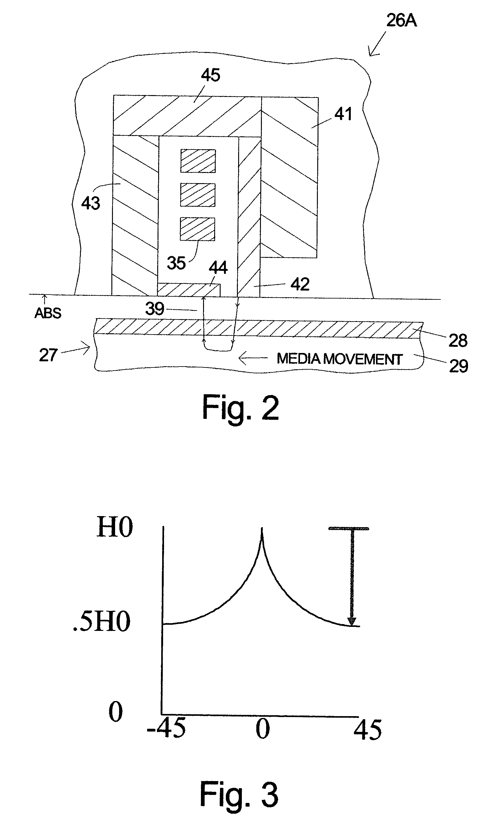
[0015]FIG. 2 is a symbolic illustration of a section of a head 26A according to the invention. The section is taken perpendicular to the ABS. This figure and the others included herein are not to scale, in part because the smaller components and spacings would be unclear. Places where the relative sizes and dimensions are significant will be noted if not known to those skilled in the art. The ABS is shown without a thin film protective overcoat which would normally be present in a production head. The term ABS as used herein means the plane as shown in the drawings without regard to whether an overcoat is present. The read sensor and its shields are not shown in FIG. 2, but could be located on either side of the write head. This design has a single coil 35. The yoke is composed of ferromagnetic pole pieces 41, 42, 43 and 46 and trailing shield 44. The trailing shield 44 can also be considered a pole piece. The movement of the magnetic recording medium is from the main pole piece 42 ...

second embodiment

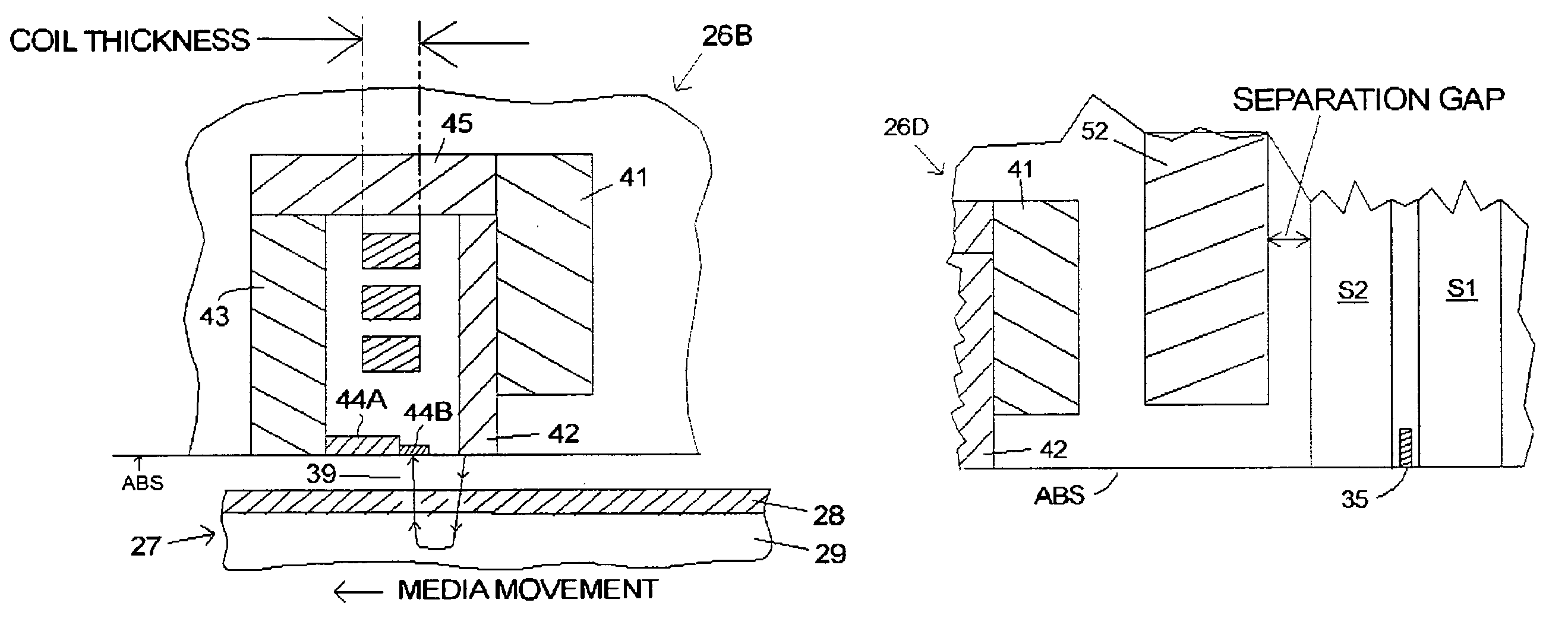
[0025]FIG. 4 is a symbolic illustration of a section of a recording head 26B according to the invention which includes a notched, two part trailing shield. The notched design has a larger maximum write field than can be achieved with the notched design. Finite element modeling has shown an 8–10% improvement in the write field. The section taken is perpendicular to the air-bearing surface. The two part trailing shield includes a pedestal 44A and a tip 44B which each have rectangular cross-sections. The tip 44B has the smaller cross-section giving the combination a “notched” appearance. FIG. 5 is an illustration of an ABS view of the recording head 26B. The cross-track width of the tip 44B is comparable to the width of the main pole piece 42 at the ABS, but the width of the pedestal 44A is much larger than the width of the tip.

[0026]The height of the tip 44B in the y-direction (orthogonal to the ABS) is preferably equal to about four write gaps to minimize write flux lost from the wri...


PUM

PropertyMeasurementUnit
thicknessaaaaaaaaaa
lengthaaaaaaaaaa
widthaaaaaaaaaa

Abstract

The invention is a magnetic transducer with separated read and write heads for perpendicular recording. The write head has a trailing shield that extends from the return pole piece toward the main pole piece to form the write gap at the air-bearing surface. One embodiment of the trailing shield is a two part structure with a pedestal and a much smaller tip that confronts the main pole piece at the gap. In one embodiment a sink of non-magnetic, electrically conductive material is disposed in the separation gap between the read head and the flux bearing pole piece. The sink is preferably made of copper and does not extend to the ABS.

Description

FIELD OF THE INVENTION[0001]The invention relates to thin film magnetic transducers for perpendicular recording and more particularly to the inductive write head portion of the transducer and even more particularly to the design of the pole pieces for the inductive write head.BACKGROUND OF THE INVENTION[0002]In a typical prior art magnetic disk recording system a slider containing magnetic transducers for reading and writing magnetic transitions flies above the disk while it is being rotated by a spindle motor. The disk includes a plurality of thin films and at least one ferromagnetic thin film in which the recording (write) head records the magnetic transitions in which information is encoded. The magnetic domains in the media on can be written longitudinally or perpendicularly. The read and write head portions of the slider are built-up in layers using thin film processing techniques. Typically the read head is formed first, but the write head can also be fabricated first. The con...

Claims


Application Information

Patent Timeline
Patent Type & Authority Patents(United States)
IPC IPC(8): G11B5/147G11B5/187G11B5/31G11B5/60H05K1/02
CPCG11B5/11G11B5/1278G11B5/6005G11B5/3116G11B5/3146G11B5/31G11B5/315G11B5/187H05K1/02
Inventor HSU, YIMINLE, QUANGLEE, HIN PONG EDWARDNIX, JAMES LAMARPENTEK, ARONRUBIN, KURTSMITH, NEILSUN, NIAN XIANGWERESIN, WALTER EUGENEWILLIAMS, MASON LAMAR
Owner WESTERN DIGITAL TECH INC
Why Eureka
Try Eureka