Thin film magnetic head having improved thermal characteristics, and method of manufacturing

a thin film, magnetic head technology, applied in the direction of magnetic recording, data recording, instruments, etc., can solve the problems of adversely affecting the performance of a media drive, adverse consequences, and near linear changes in resistance, so as to improve the thermal contact noise, increase the bias current, and enhance the heat flow

Inactive Publication Date: 2006-03-07
ORACLE INT CORP
View PDF19 Cites 11 Cited by
  • Summary
  • Abstract
  • Description
  • Claims
  • Application Information

AI Technical Summary

Benefits of technology

[0011]It is another object of the present invention to provide an improved environment for an MR element that is used for reading data from a storage media.
[0012]It is yet another object of the present invention to provide an MR element having improved thermal characteristics.
[0014]In accordance with the invention, a thin film head is provided having one or more MR elements. A thermally conductive stud is incorporated in an underlayer of the head, below the bottom shield of the MR element. This stud acts as a heat sink, and enhances the heat flow from the bottom shield to the substrate to thereby reduce thermal contact noise in the device, as well as allowing use of higher bias currents when reading signals from the media.

Problems solved by technology

Thus, small changes about a zero magnitude applied external field result in nearly linear changes in resistance.
There are many variables that can adversely affect the performance of a media drive such as a disk drive or tape drive.
Temperature variations of the MR element are one such variable with adverse consequences.
Similarly, decreases in the temperature of an MR element can cause a decrease in the resistance of the MR element.
Since the read voltage signal is proportional to variations in resistance of the MR element multiplied by the constant bias current, whenever the temperature of the MR element is increased or decreased, a thermal signal is generated which adversely adds or subtracts to the value of the desired analog signal being read.
Contact noise occurs when a bump on the tape hits the MR element (or shield adjacent thereto) and momentarily cools the device.
This cooling causes a momentary decrease in resistance of the MR element, and thereby produces a voltage spike in the output of the element.
This spike, if it is large enough, can cause errors in reading the data by the data channel.
Therefore, one factor that produces excessive contact noise is excessive MR element / shield temperature.
As track widths are narrowed and read sensors thinned, current density becomes an issue.

Method used


Image

  • Thin film magnetic head having improved thermal characteristics, and method of manufacturing
  • Thin film magnetic head having improved thermal characteristics, and method of manufacturing
  • Thin film magnetic head having improved thermal characteristics, and method of manufacturing

Examples


Embodiment Construction

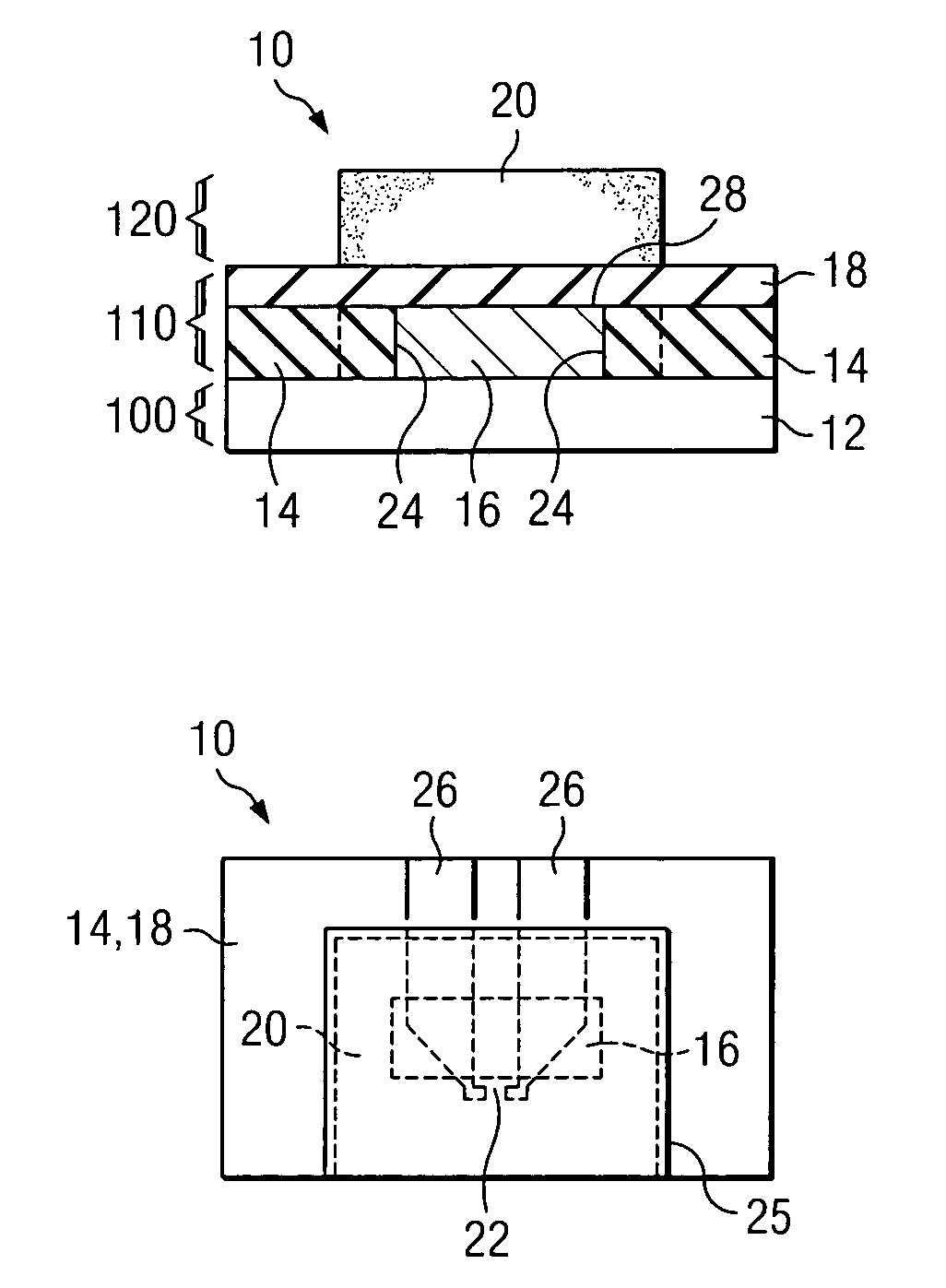
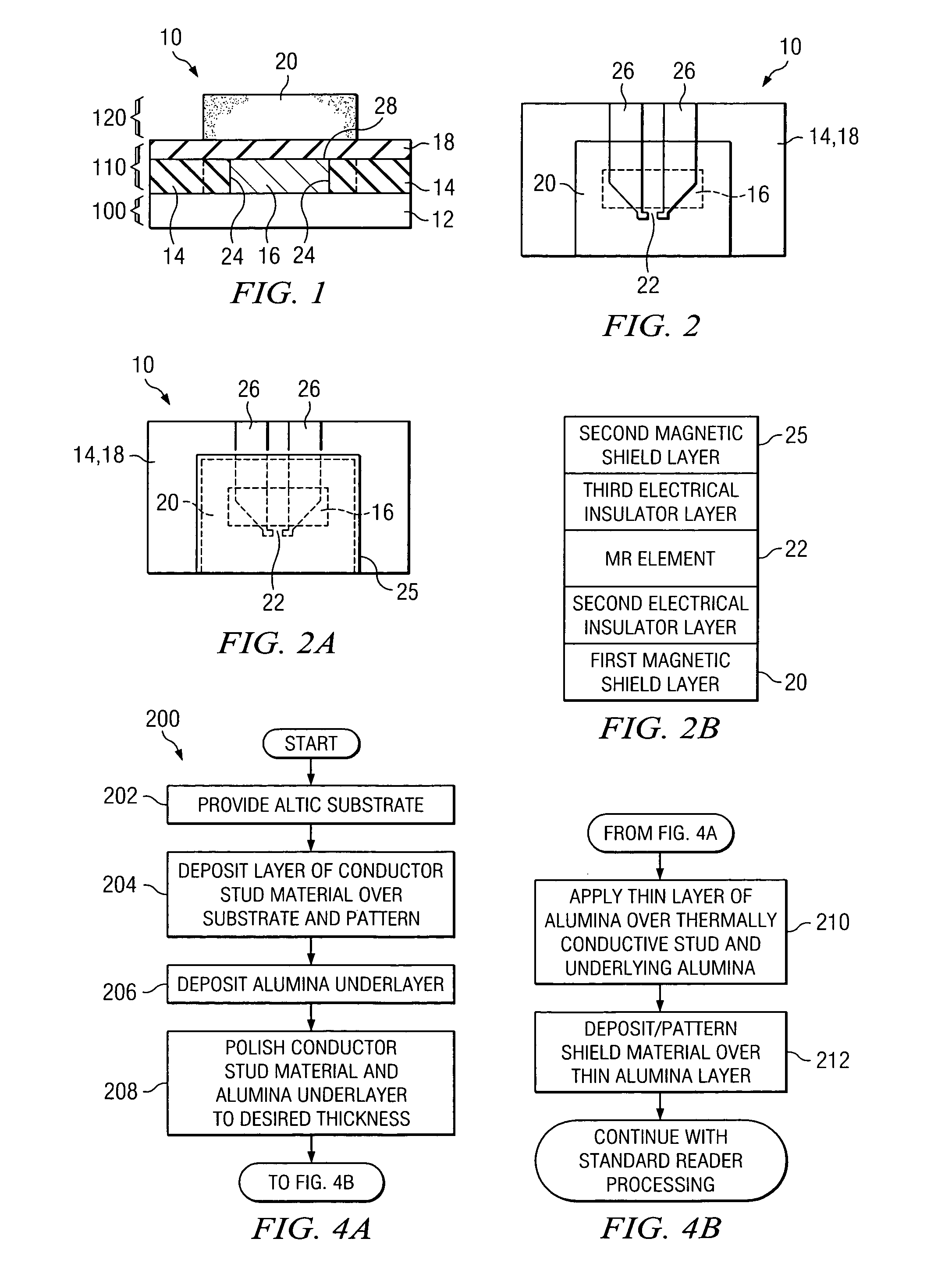
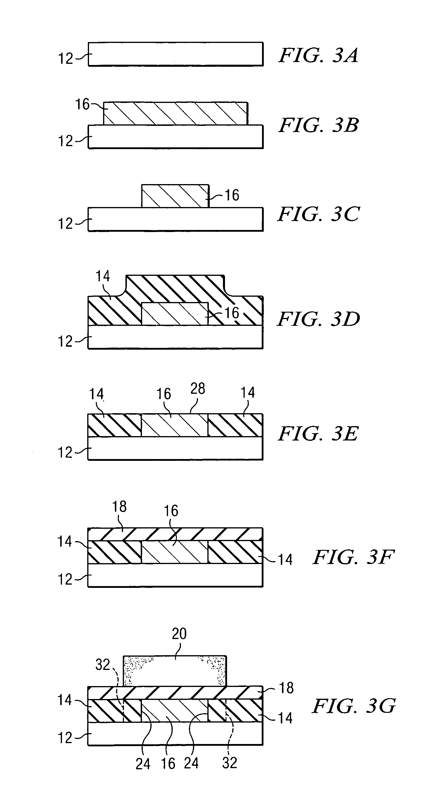
[0021]Referring now to FIG. 1, a side view of a partial MR head is generally shown at 10. The MR element is not shown in this particular view, for better clarity in showing the details of the underlying conductive stud. Starting at the bottom and working up, thin-film head 10 comprises layer 100 that includes substrate 12, which is preferably composed of an AlTiC composite material. Above layer 100 is layer 110, which is preferably composed of an underlayer alumina portion 14, a thermally conductive stud 16, and an insulator alumina portion 18. Above layer 110 is layer 120, which comprises bottom shield 20, composed of a magnetically soft material such as CZT, FeN, NiFe, etc. Insulator alumina portion 18 insulates the thermally conductive stud 16 from bottom shield 20. However, other materials exhibiting similar insulating properties could also be used, such as SiC and aluminum nitride.

[0022]Referring now to FIG. 2, a top view of a partial thin-film head 10 is depicted. The underlyi...


PUM

PropertyMeasurementUnit
thermally conductiveaaaaaaaaaa
electrical insulationaaaaaaaaaa
electrical insulatoraaaaaaaaaa

Abstract

A thin film magnetic head having one or more magneto-resistive (MR) elements. A thermally conductive stud is incorporated in an underlayer of the head, below the bottom shield of the MR element. This stud acts as a heat sink, and enhances the heat flow from the bottom shield to the substrate to thereby reduce thermal contact noise in the device, as well as allowing use of higher bias currents when reading signals from the media.

Description

FIELD OF THE INVENTION[0001]The present invention relates to magnetic storage devices, and more particularly, to magnetic storage devices which employ thin-film magnetic heads having one or more magneto-resistive (MR) transducer elements.BACKGROUND OF THE INVENTION[0002]Various types of magnetic storage devices employ thin-film heads, such as disk drives and tape drives. The thin-film head is typically composed of one or more read elements and one or more write elements used to read / write information on the tape media, such as that described in U.S. Pat. No. 5,963,401 entitled “Magnetic tape head assembly including modules having a plurality of magneto-resistive head elements” by Richard Dee et al., which is hereby incorporated by reference as background material. Writing is performed by delivering a write signal to one of the write elements. The write signal creates a variable magnetic field at a gap portion of the write element. This magnetic field induces magnetic polarity transi...

Claims


Application Information

Patent Timeline
Patent Type & Authority Patents(United States)
IPC IPC(8): G11B5/39
CPCG11B5/3106G11B5/3948G11B5/3945G11B5/3133
Inventor ARNOLD, CARL STEPHENDENISON, EDWARD VIRGILALSTRIN, APRIL LYNN
Owner ORACLE INT CORP
Why Eureka
Try Eureka