
Bottom supported solar receiver panel apparatus and method

a solar receiver and bottom support technology, applied in the field of solar receiver panels, can solve the problems of reducing the number of valves required in comparison to the top supported receiver, requiring long pipe runs, and unable to meet the needs of large-scale conversion of solar energy into electricity, etc., to achieve the effect of reducing the length of piping, facilitating maintenance, and reducing the number of valves

Active Publication Date: 2006-03-14
SOLARRESERVE TECH +1
View PDF5 Cites 48 Cited by
  • Summary
  • Abstract
  • Description
  • Claims
  • Application Information

AI Technical Summary

Benefits of technology

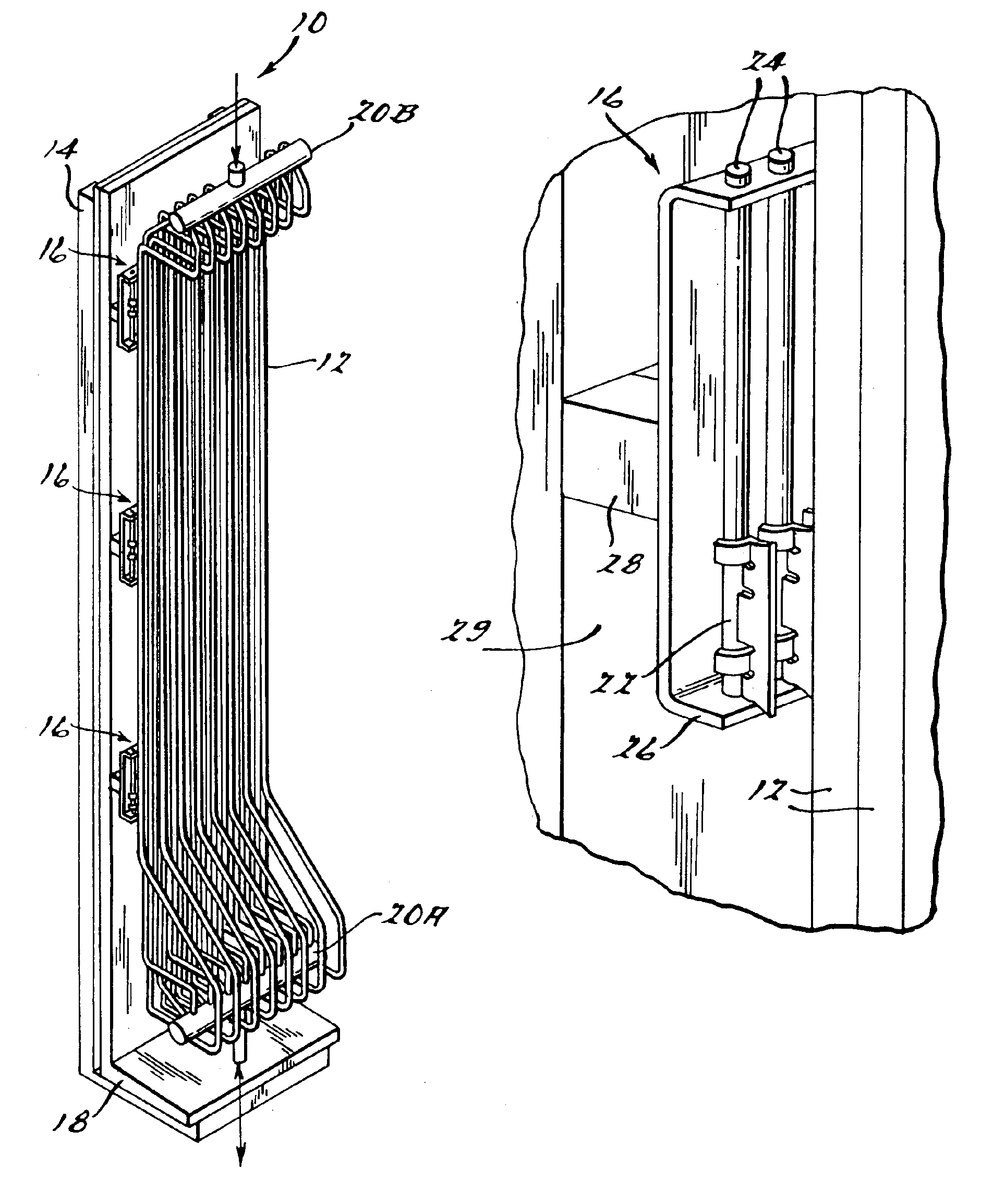
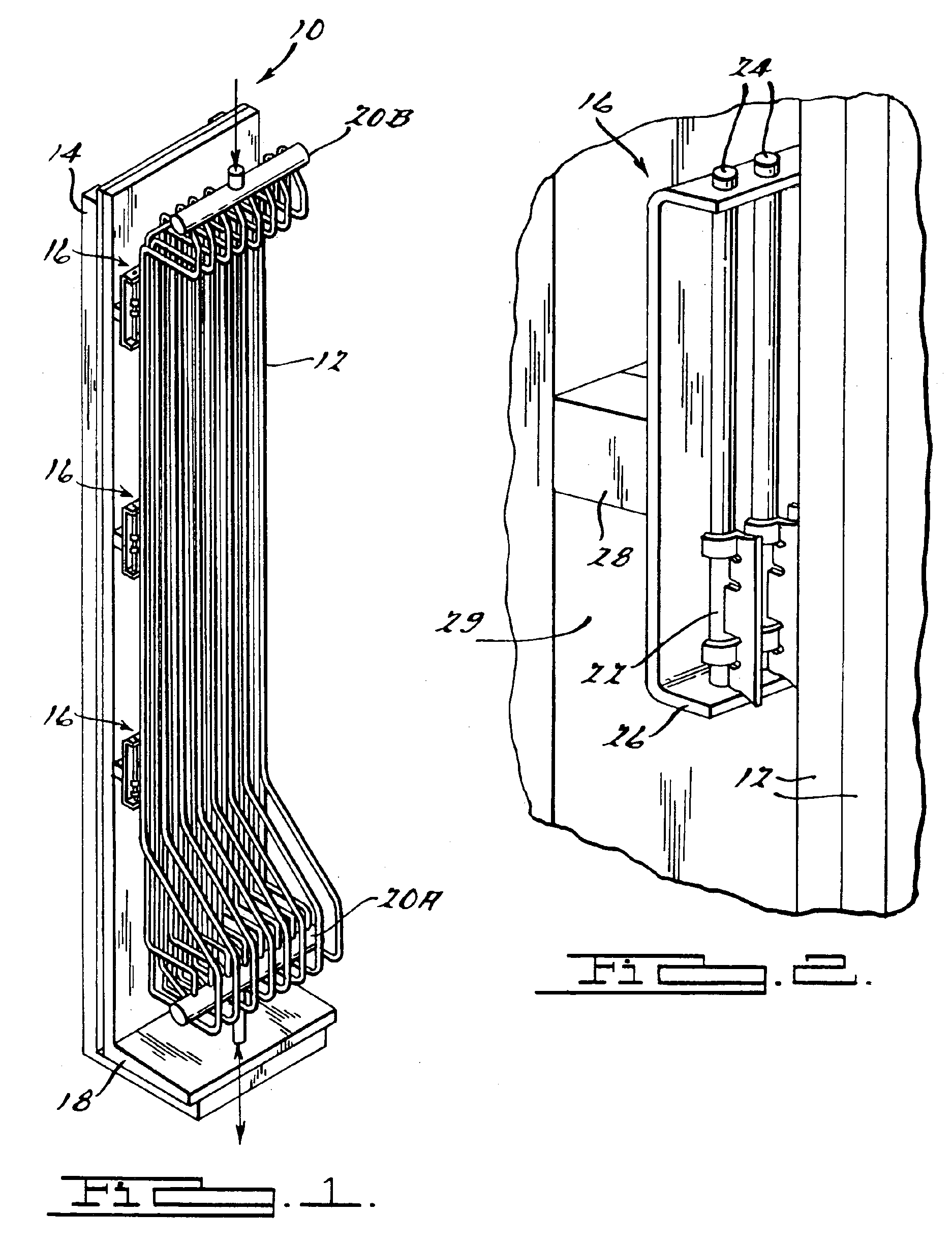
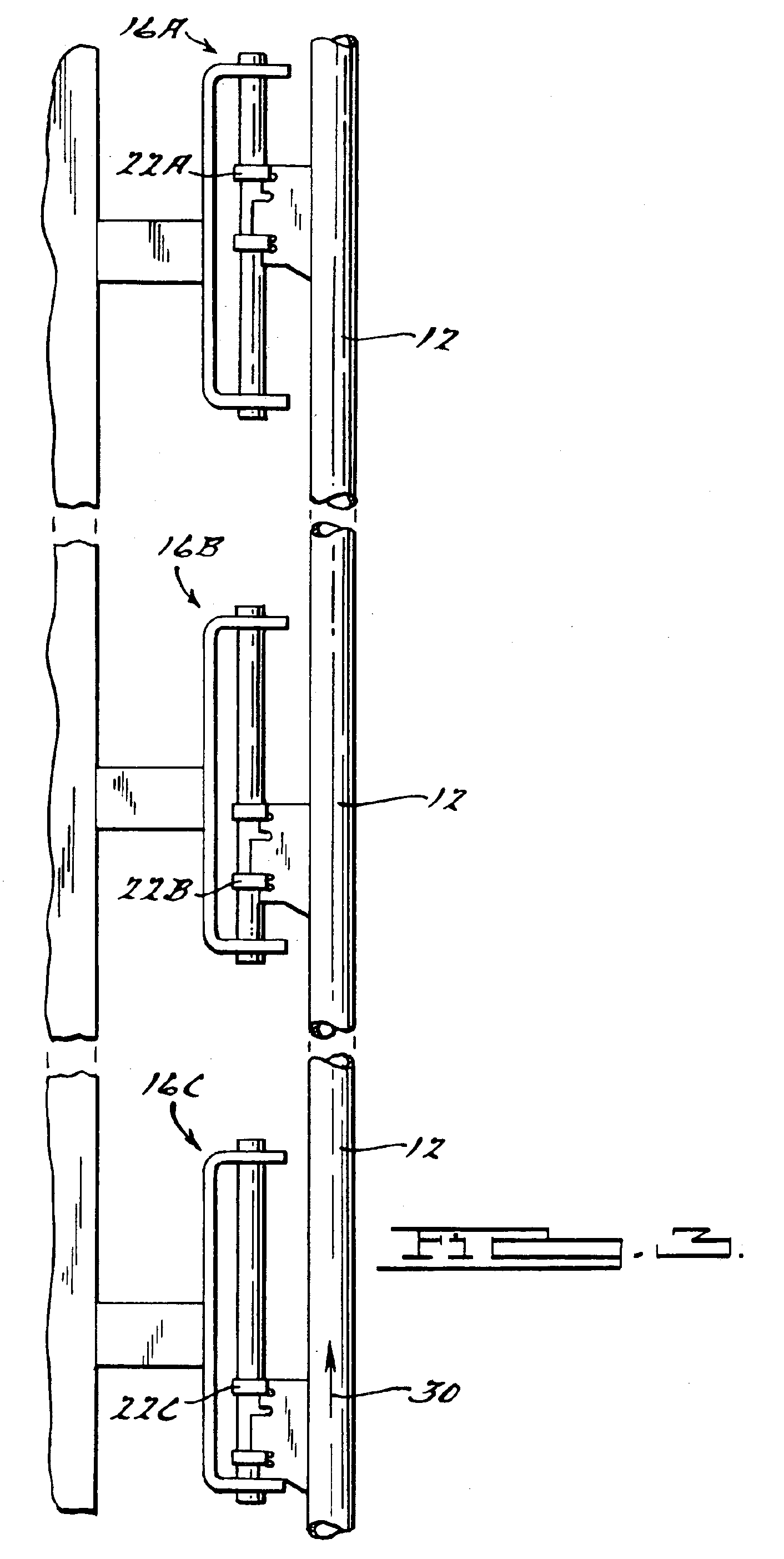
[0006]The present invention relates to a solar receiver panel having bottom supported tubes that carry heat absorbing fluid. In a preferred embodiment, the tubes are attached to the receiver panels with clips spaced apart vertically along the lengths of the tubes. A bottommost clip of each tube carries the entire vertical weight of its associated tube and header assembly. The clips allow portions of the tubes to move up and down when the tubes undergo thermal expansion and contraction. The tubes undergo thermal expansion in a vertically upward direction when the thermal fluid (e.g., molten salt or others) inside the tubes is heated by absorbing heat from the receiver panels. The bottom supported receiver panel reduces the lengths of piping required, as well as the routing complexity of the piping, within the receiver. Further, the number of valves required in comparison to the top supported receiver can be reduced. Further, the valves can be placed at a convenient location, for example, on the deck of the receiver for easy maintenance. The individual receiver panels are connected by jumper lines. Jumper lines connecting the bottoms of adjacent panels typically have drain valves located on each servicing two receiver panels. Similarly, jumper lines connecting the top of adjacent panels have vent valves. The bottom supported receiver requires a fewer number of vent and drain valves as compared to a top supported receiver.

Problems solved by technology

Engineers are facing several challenges in capturing, storing and converting solar energy.
The problem of converting solar energy into electricity in a cost-effective manner and on a large scale still poses challenges.
This arrangement also requires lengthy pipe runs.
Therefore, construction can often become complex due to the routing difficulties and lengthier pipes used within the cylindrical receiver.
Even a flat billboard shape receiver requires long runs of large pipe if the panels are top supported.

Method used


Image

  • Bottom supported solar receiver panel apparatus and method
  • Bottom supported solar receiver panel apparatus and method
  • Bottom supported solar receiver panel apparatus and method

Examples


Embodiment Construction

[0016]The following description of the preferred embodiment(s) is merely exemplary in nature and is in no way intended to limit the invention, its application, or uses.

[0017]Initially, a general description of the construction and operation of a solar power tower will be provided. A solar power tower is used to collect solar thermal energy and convert it into electricity. A large number of sun-tracking mirrors called heliostats collect the solar energy. The collected solar energy from the heliostats is redirected and concentrated onto a solar receiver mounted on top of the solar power tower. The solar receiver can be constructed by various methods. The present invention is adapted for a solar receiver that functions as a heat exchanger. The receiver functioning as a heat exchanger transfers the concentrated solar energy redirected from the heliostats to a fluid circulated through a piping system inside the receiver.

[0018]The fluid inside the receiver functions as an energy transfer ...


PUM


Abstract

A bottom supported solar receiver tube / header assembly having a bottom clip for supporting the entire load of a plurality of tubes carrying a heat absorbing fluid. The tubes are allowed to expand vertically upwardly under thermal flux conditions created when the fluid absorbs heat from the solar receiver panel. A receiver panel assembly incorporating a plurality of the bottom supported receiver tubes requires less piping than a comparably sized, conventional receiver panel assembly with top supported tubes and even better facilitates access and maintenance of valves associated with the receiver panel assembly. The invention further allows a solar receiver panel assembly to be constructed with significantly fewer drain and vent valves than previously developed, top supported receiver panel assemblies.

Description

FIELD OF THE INVENTION[0001]The present invention generally relates to solar receiver panels, and more particularly to bottom supported solar receiver panels that enable the upward thermal expansion of tubes attached to the solar receiver panels.BACKGROUND OF THE INVENTION[0002]In the backdrop of ever dwindling fossil fuel resources, researchers are exploring ways of harnessing alternate sources of energy. Solar energy is a promising alternate source of energy. Engineers are facing several challenges in capturing, storing and converting solar energy. The problem of converting solar energy into electricity in a cost-effective manner and on a large scale still poses challenges.[0003]Several approaches are being followed to reach the goal of generating a large-scale and reliable flow of electricity from solar energy. One such method is through the use of a solar central receiver mounted on top of a tower. The solar receiver is basically a heat exchanger that absorbs concentrated solar ...

Claims


Application Information

Patent Timeline
Patent Type & Authority Patents(United States)
IPC IPC(8): F24J2/24F24S10/70F24S20/20F28F9/013
CPCF24J2/07F24J2/4649F24J2/4636F28F9/013Y02E10/41F24J2002/4665F24S80/20F24S40/80F24S20/20F24S40/60F24S2025/6004Y02E10/40
Inventor LITWIN, ROBERT ZACHARY
Owner SOLARRESERVE TECH
Learn More