Socket-welded pipe joint

a joint and socket technology, applied in the direction of pipe joints, non-disconnectible pipe joints, mechanical equipment, etc., can solve the problems of loss of production and revenue, personal injury, plant shutdown, etc., and achieve the effect of reducing residual stresses, fewer failures of joints, and better fusion of metal

Inactive Publication Date: 2006-03-14
SHAH NITIN J
View PDF39 Cites 10 Cited by
  • Summary
  • Abstract
  • Description
  • Claims
  • Application Information

AI Technical Summary

Benefits of technology

[0012]The object of this invention is to provide a socket-welded pipe joint which is practical, provides better fusion of metal, and reduces residual stresses. These will result in fewer failures of the joints. In the first two embodiments, the end of fitting is configured so that the fusion of the base metal of the end portion of the fitting w...

Problems solved by technology

Failures of socket-welded connections have been identified in the past, resulting in a loss of production and revenues due to shutdown of plants.
Bursting of such a pipe segment can result in personal injury, even death.
Research...

Method used


Image

  • Socket-welded pipe joint
  • Socket-welded pipe joint
  • Socket-welded pipe joint

Examples


first embodiment

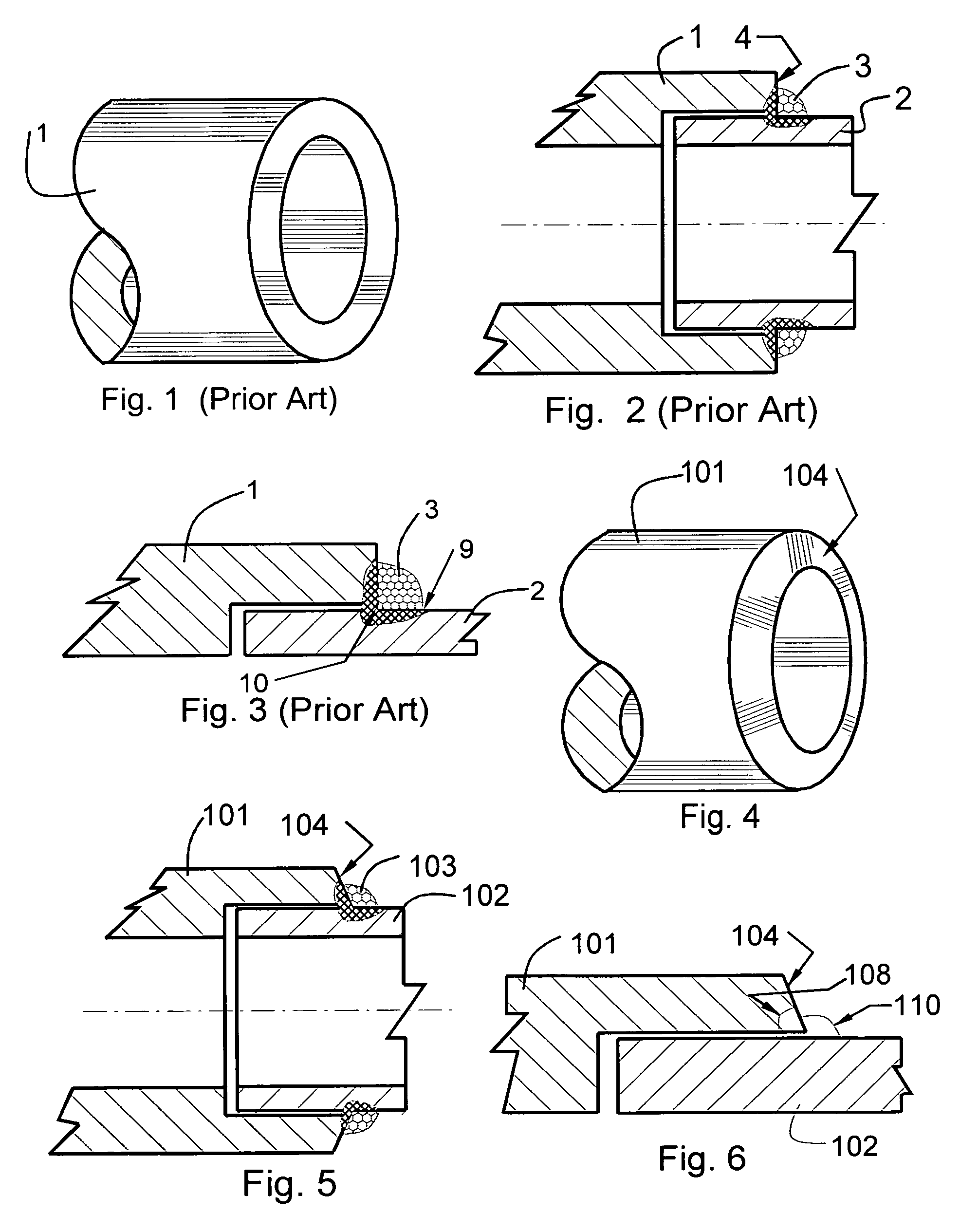
[0039]the invention is shown in FIGS. 4, 5 and 6. Similar to the prior art configuration, this embodiment has modified socket-welded fitting 101, the end of the pipe segment 102 inserted inside the socket, and a weld 103. The view in FIG. 5 is after the welding is performed with some of the pipe and fitting base metal fused. The difference between the prior art configuration shown in FIGS. 1–3, and this embodiment is that the edge 104 is chamfered as shown in FIG. 5, while prior art edge 4 shown in FIG. 2 is vertical and 90° to the wall of the pipe segment 2. (As used herein, the term “chamfer” refers to an annular surface which has been cut, or is shaped as though it had been cut, from surface which included a 90 degree angle; as viewed in cross section, the surface of the chamfer may include one or more straight lines and / or curves.) Additionally, the size and profile of the weld 103 in FIG. 5 may be different compared to the profile of the weld 3 in FIG. 2. The weld size and prof...

second embodiment

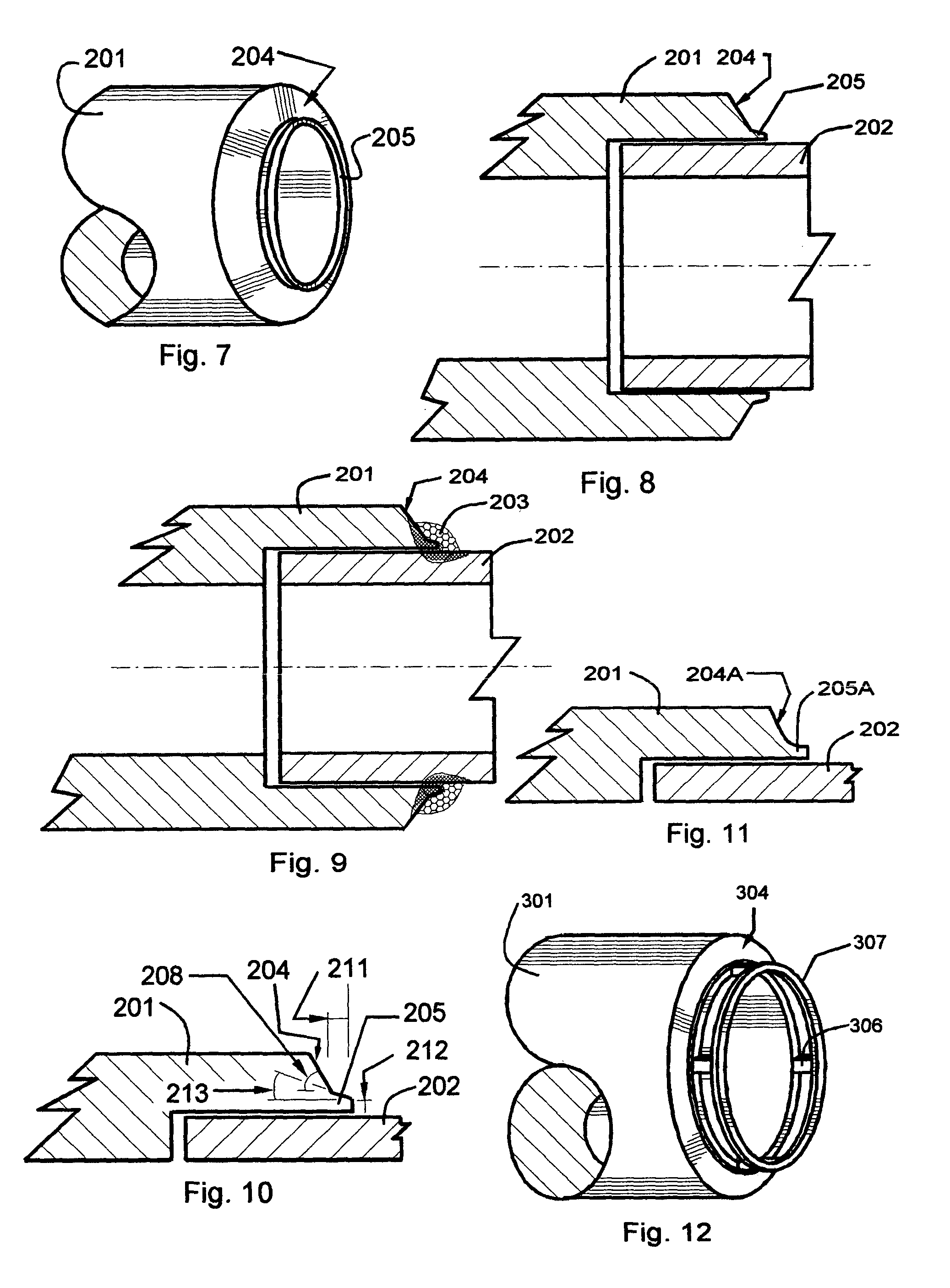
[0044]FIG. 11 shows a variation of the second embodiment in which the surface of lip 205A merges gradually into the remainder of chamfered edge 204A. That is, the profile of the major portion of the chamfered edge is a curve rather than two intersecting straight lines.

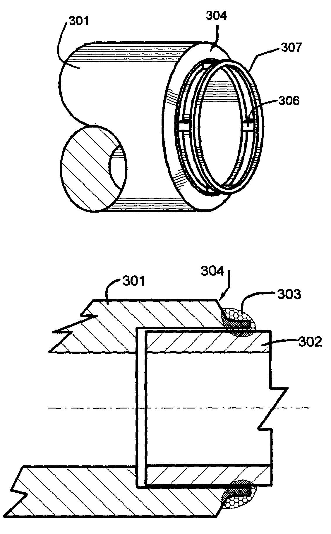
[0045]The third embodiment is shown in the FIGS. 12, 13, 14 and 15. Similar to the second embodiment, this embodiment has modified socket-welded fitting 301, the end of the pipe segment 302 inserted inside the socket, and a weld 303. Chamfered edge 304 includes inwardly flared surface 305 and thin metal bars 306 extending parallel to the longitudinal axis. The size and number of the bars will be based on the diameter and the thickness of the pipe segment 302 and the necessary strength of the weld joint. Chamfered edge 304 also includes a ring 307, which provides better fusion and reduces residual stresses at the toe of the weld. The metal bars 306 are provided to connect the ring 307 to, and accurately spaces it from, ...

third embodiment

[0046]The advantage of this third embodiment is that more heat of the welding will be used in melting the base metal of the flared surface 305, metal bars 306, and the metal ring 307, as well as some of the base metal of the remaining, larger diameter portion of edge 304, thereby reducing the residual stresses and providing better fusion. This embodiment will also provide reduction in the failure initiated at the toe of the weld 303 in addition to reducing failure at the root. However, this embodiment is slightly more complicated than the first two embodiments.

[0047]The fourth embodiment is shown in FIGS. 16, 17, 18 and 19. Similar to the third embodiment, this embodiment has modified socket-welded fitting 401, the end of the pipe segment 402 inserted inside the socket, and a weld 403. Chamfered edge 404 includes inwardly flared surface 405 and thin metal bars 406 extending parallel to the longitudinal axis. The size and number of the bars will be based on the diameter and the thick...


PUM


Abstract

A welded pipe joint having reduced internal stresses comprises a pipe, a socket fitting, and an annular weld. The end surface of the fitting is chamfered, preferably in a concave profile, so that the weld profile subtends an angle of from about 100 degrees to about 120 degrees, rather than the customary 90 degrees. The pipe has no dam or other protuberance to confine the bead of added metal. Prior to welding, the fitting may have an annular lip immediately surrounding the surface of the pipe and may also have a ring spaced from the lip. The ring may be integral with the fitting and spaced from the lip by thin, radially spaced metal bars or may be separate from the fitting.

Description

RELATED APPLICATIONS[0001]This application discloses and claims subject matter which was disclosed in provisional patent application Ser. No. 60 / 418,061 filed Oct. 11, 2002 and provisional patent application Ser. No. 60 / 449,471 filed Feb. 24, 2003, both of which provisional applications are titled “Socket Welded Joint”.TECHNICAL FIELD[0002]This invention pertains to the field of welding metal pipe segments and metal pipe fittings to each other and to equipment.BACKGROUND[0003]In plants such as power plants, process plants, and the like, it is necessary to transfer fluids, including liquids, gases, and fluidized solids, from one location to another, and between different equipment. This is accomplished by piping layouts. When a piping layout is created, it must provide for changing directions of the piping, connecting two or more pipe segments, and / or connecting pipe segments to equipment components or fittings.[0004]Based on issued patents relating to welding and pipe connections, a...

Claims


Application Information

Patent Timeline
IPC IPC(8): F16L13/02
CPCF16L13/0209
Inventor SHAH, NITIN J.
Owner SHAH NITIN J
Why Eureka
Try Eureka