
Device for implanting catheters

a technology for implanting catheters and catheters, which is applied in the direction of intravenous devices, guide needles, infusion syringes, etc., can solve the problems of endanger the implantation position of implanted catheters, and achieve the effect of facilitating device handling and simplifying the handleability of the devi

Inactive Publication Date: 2006-03-14
BIOTRONIK MESS UND THERAPIEGERAETE GMBH & CO
View PDF20 Cites 10 Cited by
  • Summary
  • Abstract
  • Description
  • Claims
  • Application Information

AI Technical Summary

Benefits of technology

[0011]The advantages which the present invention entails are in particular that the implantation device is cut open by pulling the wire from the distal end towards the proximal end and thus is firstly cut open over the entire length. In that way friction between the implantation device and the implanted catheter is reduced and the operation of withdrawing of the implantation device after implantation of the catheter has been effected does not result in the implantation location and / or the implantation position of the catheter being endangered.
[0012]The fact that the tube is gradually cut open along its length means that the wire and the wall of the tube are exposed to substantially lower levels of stress, thereby preventing elastic deformation which in turn can endanger the implantation position of the implanted catheter.
[0015]In a preferred embodiment of the invention the device has two arms or plates at the proximal end of the tube. The arms serve to simplify handleability of the device, in particular when cutting it open. The provision of the two arms means that the operator can better hold the device firmly by means of the two arms when cutting it open.
[0016]In a further preferred embodiment of the invention the wire has a handle at its second end. By pulling on the handle the implantation device can be cut open from the distal end to the proximal end, which also facilitates handling of the device.

Problems solved by technology

The fact that the tube is gradually cut open along its length means that the wire and the wall of the tube are exposed to substantially lower levels of stress, thereby preventing elastic deformation which in turn can endanger the implantation position of the implanted catheter.

Method used


Image

  • Device for implanting catheters
  • Device for implanting catheters

Examples


Embodiment Construction

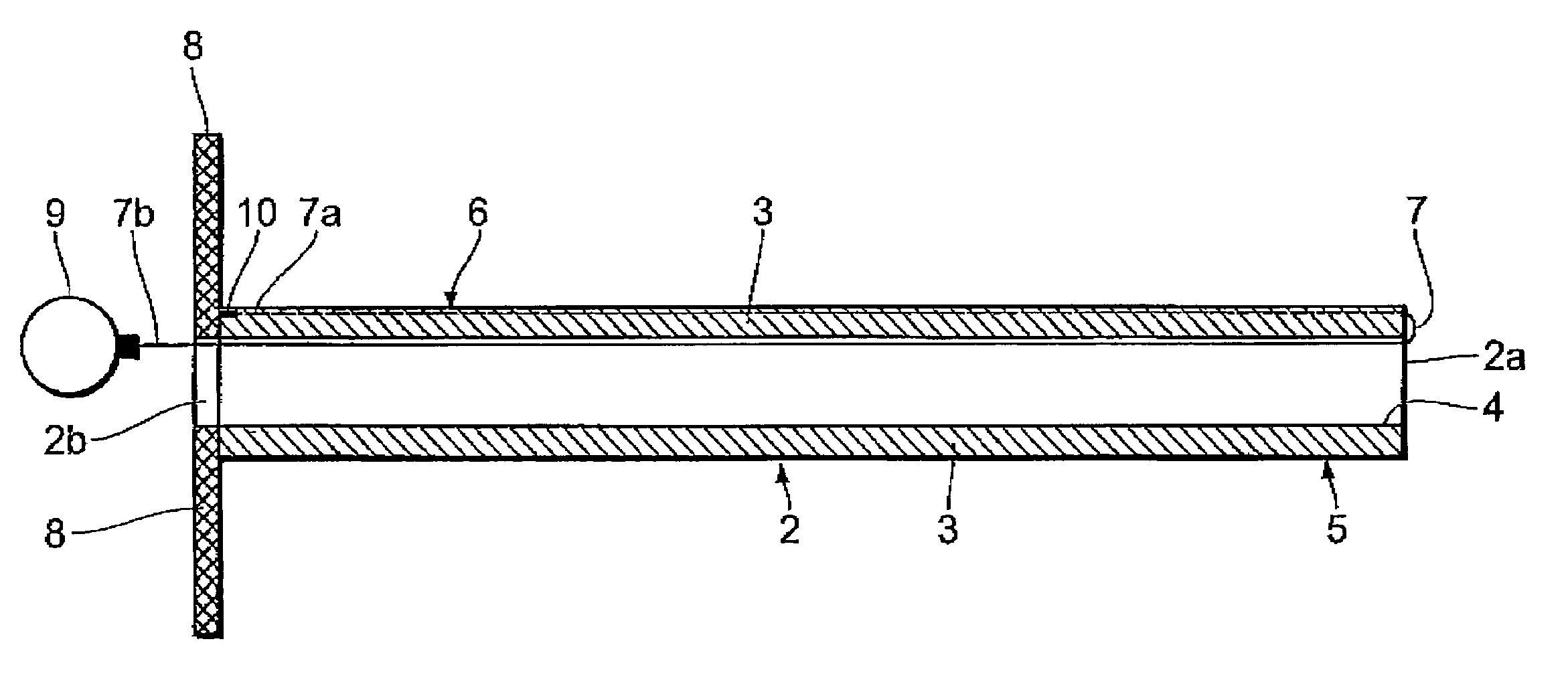
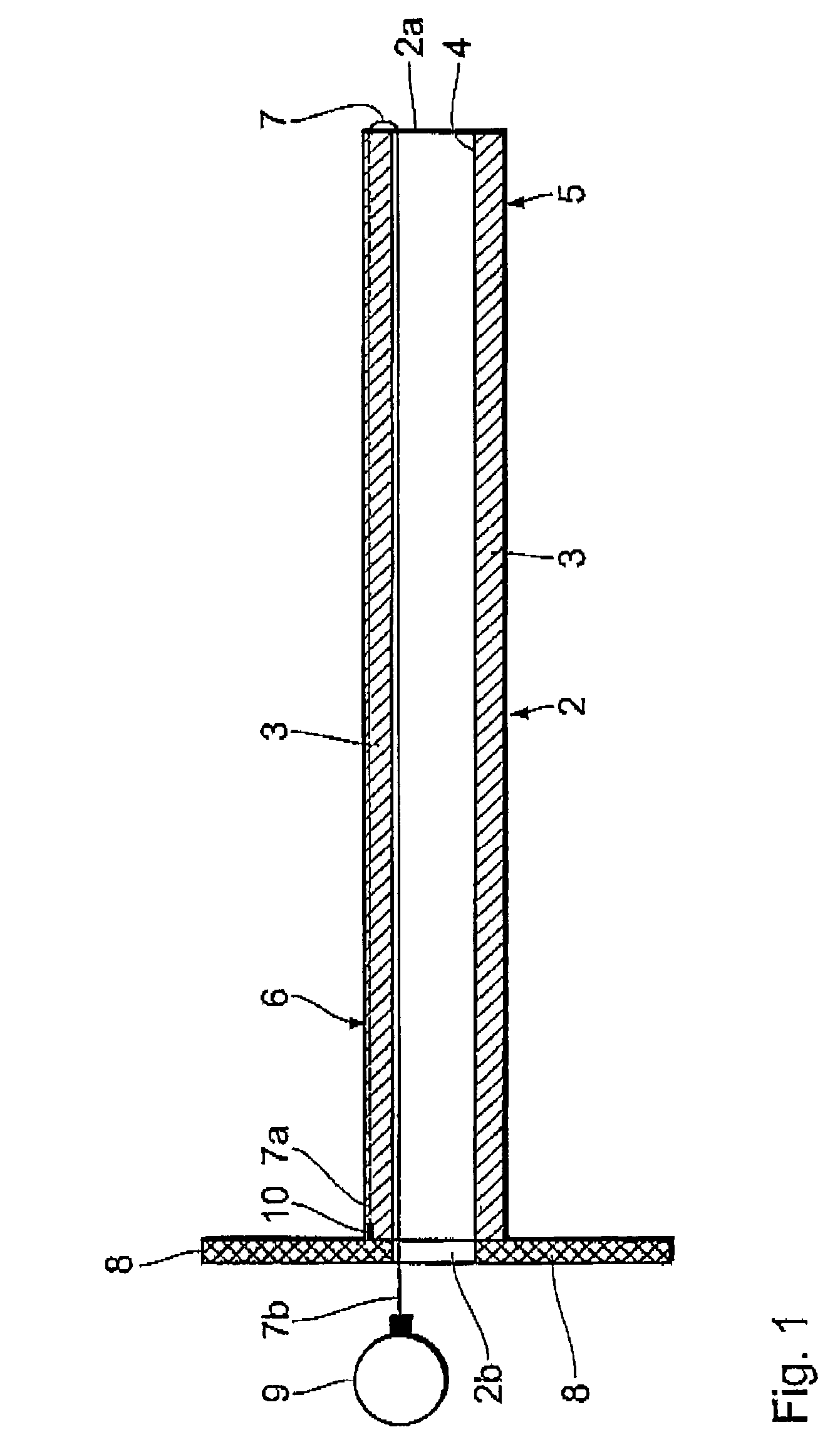
[0021]FIG. 1 shows a tube 2 with a wall 3 and two arms 8 arranged at the proximal end 2b thereof. In addition at an outside surface 5 of the wall 3 the tube 2 has a longitudinal slot 6 along its longitudinal direction. The first end 7a of a wire 7 is fixed at a location 10 at the proximal end 2b of the tube 2. The wire 7 is then guided in the longitudinal slot 6 from the proximal end 2b of the tube 2 to the distal end 2a thereof. The wire 7 is then passed at the distal end 2a of the tube 2 around the distal end 2a and guided back at the inside surface 4 of the wall 3 from the distal end 2a of the tube 2 to the proximal end 2b thereof.

[0022]In that arrangement the length of the wire 7 is so selected that the second end 7b of the wire 7 projects out of the proximal end 2b of the tube 2. A handle 9 is preferably fixed to that second end 7b of the wire 7.

[0023]By applying a pulling force to the cable the wire 7 is pulled in the proximal direction and in that situation cuts through the w...


PUM


Abstract

A device for implanting catheters has a tube with a wall and a wire. The tube is intended to be introduced into a body so that at least one catheter can be inserted for implantation through the tube. The wall of the tube has an inside surface and an outside surface. The wire is preferably fixed at its first end in the region of the proximal end of the tube to the inside surface or the outside surface of the wall and the wire is guided in the proximity of that surface along the longitudinal direction of the tube from the proximal end of the tube to the distal end thereof and is then returned in the proximity of the respective other surface of the wall along the longitudinal direction from the distal end of the tube to the proximal end thereof. The wire is used to cut the tube open after insertion of the catheter.

Description

[0001]The present invention concerns a device for implanting catheters having a tube with a wall which has inside surface and an outside surface and which encloses a cavity open both at the proximal end and at the distal end and which is adapted to be inserted into a body so that at least one catheter can be inserted for the implantation procedure through the tube. For that purpose the tube is of a length which is such that the proximal end of the tube remains outside a body of a patient upon insertion of a catheter.BACKGROUND OF THE ART[0002]Insertion cannulae are used to produce openings in the skin for the insertion of various medical devices into soft tissue or organs. For example an insertion cannula can be inserted through a needle puncture and a catheter can then be inserted by means of the cannula through the skin into the patient. After insertion of the catheter the cannula is removed from the patient again. In general terms in that respect the catheter is connected to a me...

Claims


Application Information

Patent Timeline
IPC IPC(8): A61M5/178A61M25/06
CPCA61M25/0668A61M2025/0675
Inventor BRESKOT, TOBIASSCHALDACH, JR., LEGAL REPRESENTATIVE, MAXSCHALDACH, DECEASED, MAX
Owner BIOTRONIK MESS UND THERAPIEGERAETE GMBH & CO
Learn More