
Induction logging antenna

a technology of induction logging and antenna, which is applied in the direction of measurement devices, acoustic wave reradiation, electric/magnetic detection for well-logging, etc. it can solve the problems of inability to employ magnetic materials in induction logging tools, drilling environments, and reducing the accuracy of logging measurement, so as to reduce the stress on the magnetic core

Inactive Publication Date: 2006-03-14
GEOLINK UK
View PDF13 Cites 22 Cited by
  • Summary
  • Abstract
  • Description
  • Claims
  • Application Information

AI Technical Summary

Benefits of technology

[0007]The invention seeks to provide an improved antenna assembly which can provide suitable protection of the magnetic core under shock and vibration and axial thermal expansion of supporting materials i.e. to minimise stresses on the magnetic cores. This is an important objective since the permeability of the cores is a complex function which includes the stresses observed by the material, and a change in the permeability of the material results in a change in the self inductance of the antenna. These stresses may arise from several sources e.g. hydrostatic pressure, thermal expansion of supporting structures and shock and vibration.
[0015]The configuration of the antenna assembly serves to reduce stresses induced by local environmental conditions and their effect on other significant antenna variables, such as effective antenna aperture / area, and self inductance.
[0016]Preferably, the magnetic cores are MPP cores and which, advantageously, undergo special processing prior to final assembly. The purpose of the processes is threefold: to optimise the magnetic coupling between the individual cores (and hence optimise effective permeability), and to relieve post machining stresses, and reduce local stresses on the magnetic core surface when held in compression, maintaining stability. The process involves machining and “lapping” the toroidal cores to maximise the magnetic coupling area between them and produce an accurate surface finish at the interface between the cores, followed by a temperature cycle annealing process to reduce stresses built up during the machining process.

Problems solved by technology

Conventional wisdom suggests that it is not possible to employ magnetic material in an induction logging tool, in a drilling environment, and while maintaining electrical stability of the antenna assembly.
Typically, antenna instability in an induction logging instrument results in diminished accuracy of the measurement.
In addition, typically antenna instability in an induction logging instrument results in diminished accuracy of the logging measurement.
Furthermore, MPP (molypermalloy)- used in logging tools, is a brittle material and is at risk of being damaged in a drilling environment.

Method used


Image

  • Induction logging antenna
  • Induction logging antenna
  • Induction logging antenna

Examples


Embodiment Construction

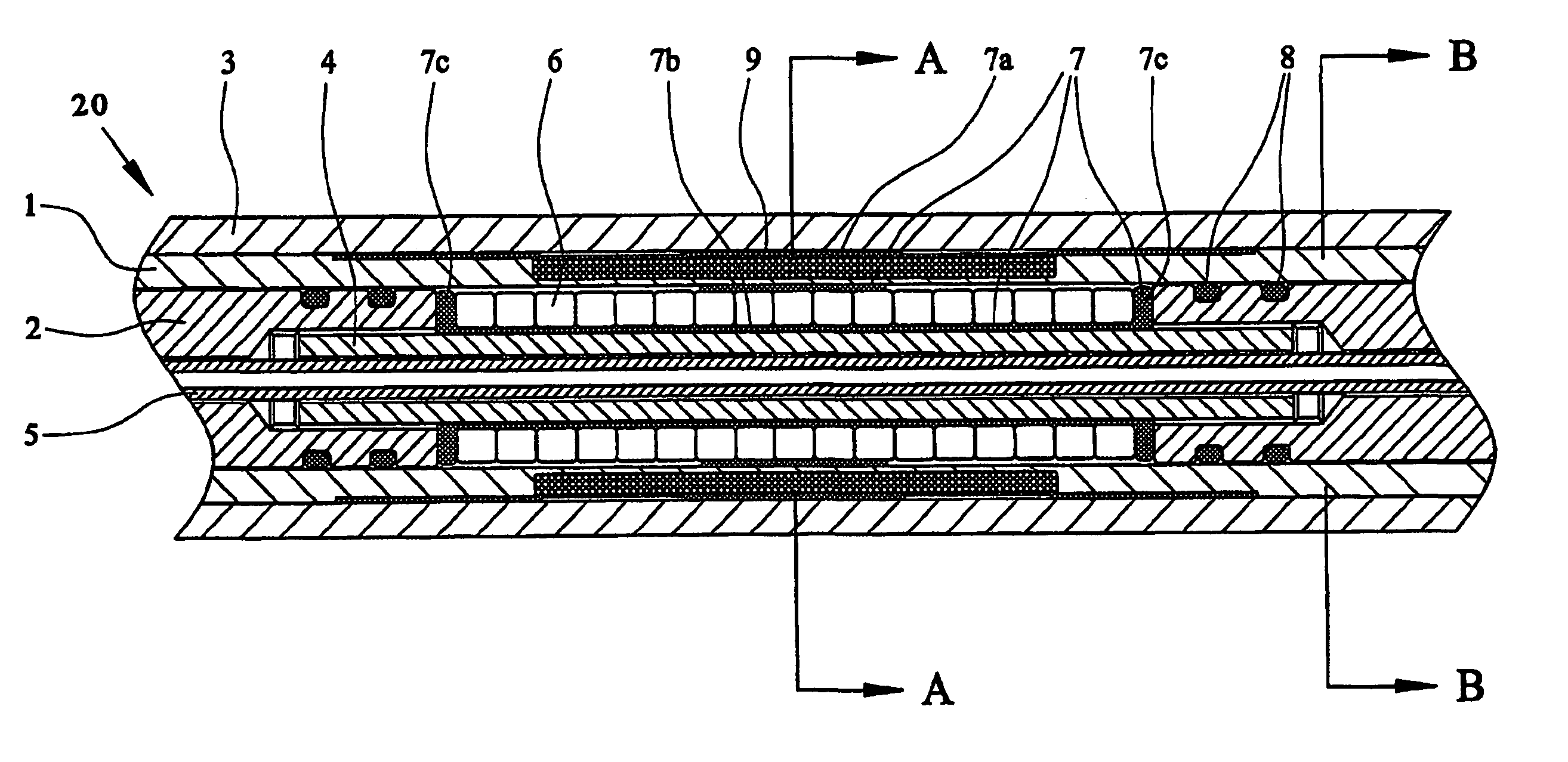
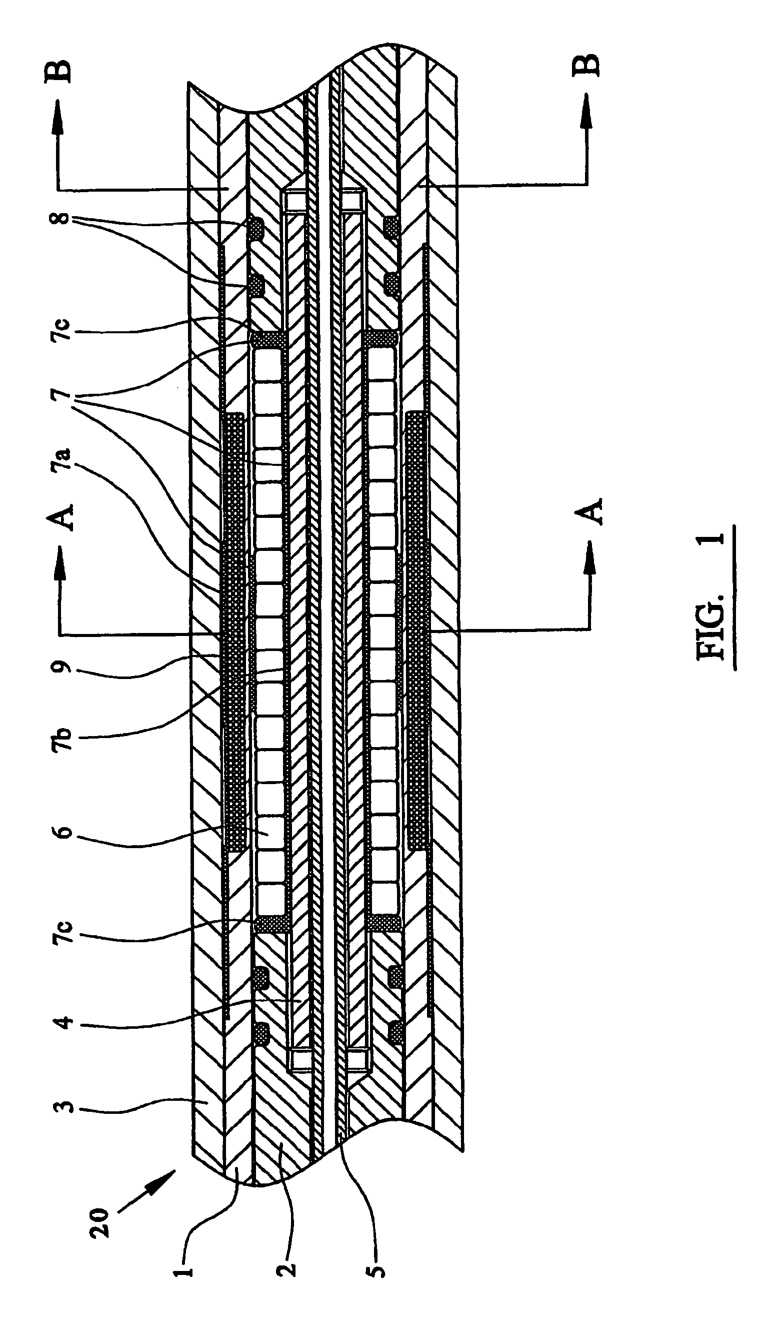
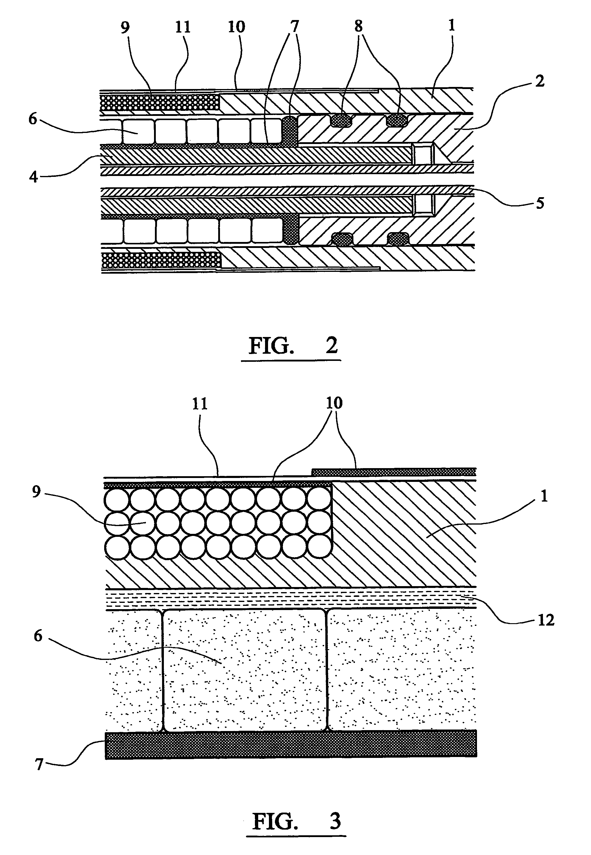
[0025]Referring now to FIGS. 1 to 4 of the drawings, there is shown an antenna assembly for an induction logging tool (for use in drilling operations) and which has been designed to maintain its electrical integrity (and hence the accuracy of the logging tool), despite the adverse environmental factors which prevail in a typical drilling situation.

[0026]The antenna assembly is designated generally by reference 20, and has been designed specifically for use with an induction logging tool of the general type disclosed in U.S. Pat. No. 6,100,696 or PCT / GB00 / 02510.

[0027]The assembly has an outer pressure housing 3, and toroidal magnetic cores 6 of MPP (molypermalloy) which are mounted in shock-resistance manner in the housing. Shock-absorbing mountings 7 mount the cores 6 in the housing 3, and are made of VITON or NITRILE (Trade Mark) elastomer.

[0028]Further components of the assembly 20 include a coil former 1 made of cylindrical epoxy glass fibre tube, and core spacers 2 which are thi...


PUM


Abstract

An antenna assembly for an induction logging tool for use in a drilling operation. The assembly includes an outer pressure housing, a coil former within the pressure housing, magnetic cores mounted in the housing, a core carrier within the coil former and the pressure housing which carries the magnetic cores, and shock-absorbing mountings on the core carrier for the magnetic cores.

Description

BACKGROUND OF THE INVENTION[0001]This invention relates to an antenna assembly for an induction logging tool.[0002]The invention has been developed primarily, though not exclusively, with a view to provide an improved antenna assembly for an induction logging tool of the general type disclosed in more detail in U.S. Pat. No. 6,100,696 and PCT / GB00 / 02510. However, the improved antenna assembly of the invention is applicable generally to induction logging tools.[0003]In designing an antenna assembly for an induction logging tool, consideration has to be given to the external environmental conditions which prevail during a typical drilling situation e.g. pressures of up to 20,000 p.s.i., temperatures ranging from −35° C. to +175° C., and shock and vibration to 1000 g. Despite the environmental factors it is important to maintain electrical stability, and in particular self inductance of the tool in order to achieve accurate logging.[0004]Conventional wisdom suggests that it is not poss...

Claims


Application Information

Patent Timeline
Patent Type & Authority Patents(United States)
IPC IPC(8): G01V3/08G01V3/10G01V3/12G01V3/18G01V3/28
CPCG01V3/28
Inventor ALLAN, VICTOR
Owner GEOLINK UK
Learn More