
Current steering charge pump having three parallel current paths preventing the current sources and sinks to turn off and on

a charge pump and current steering technology, applied in the direction of angle demodulation by phase difference detection, automatic control, instruments, etc., can solve the problems of residual charge being left in the loop filter, asymmetrical sink and source current waveform, and producing non-smooth control voltage and spur frequency tones

Inactive Publication Date: 2006-03-14
AVAGO TECH WIRELESS IP SINGAPORE PTE
View PDF11 Cites 36 Cited by
  • Summary
  • Abstract
  • Description
  • Claims
  • Application Information

AI Technical Summary

Benefits of technology

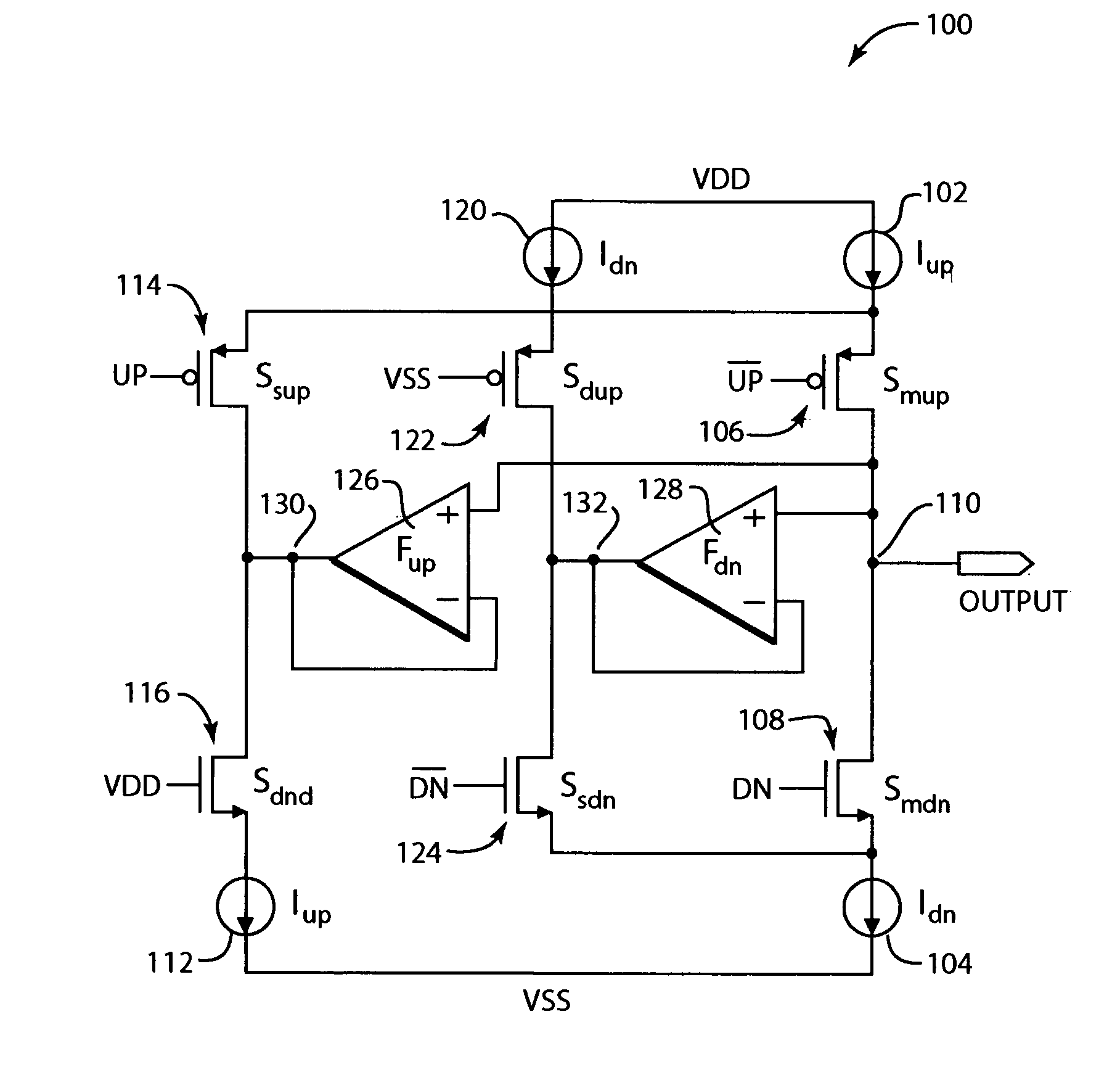
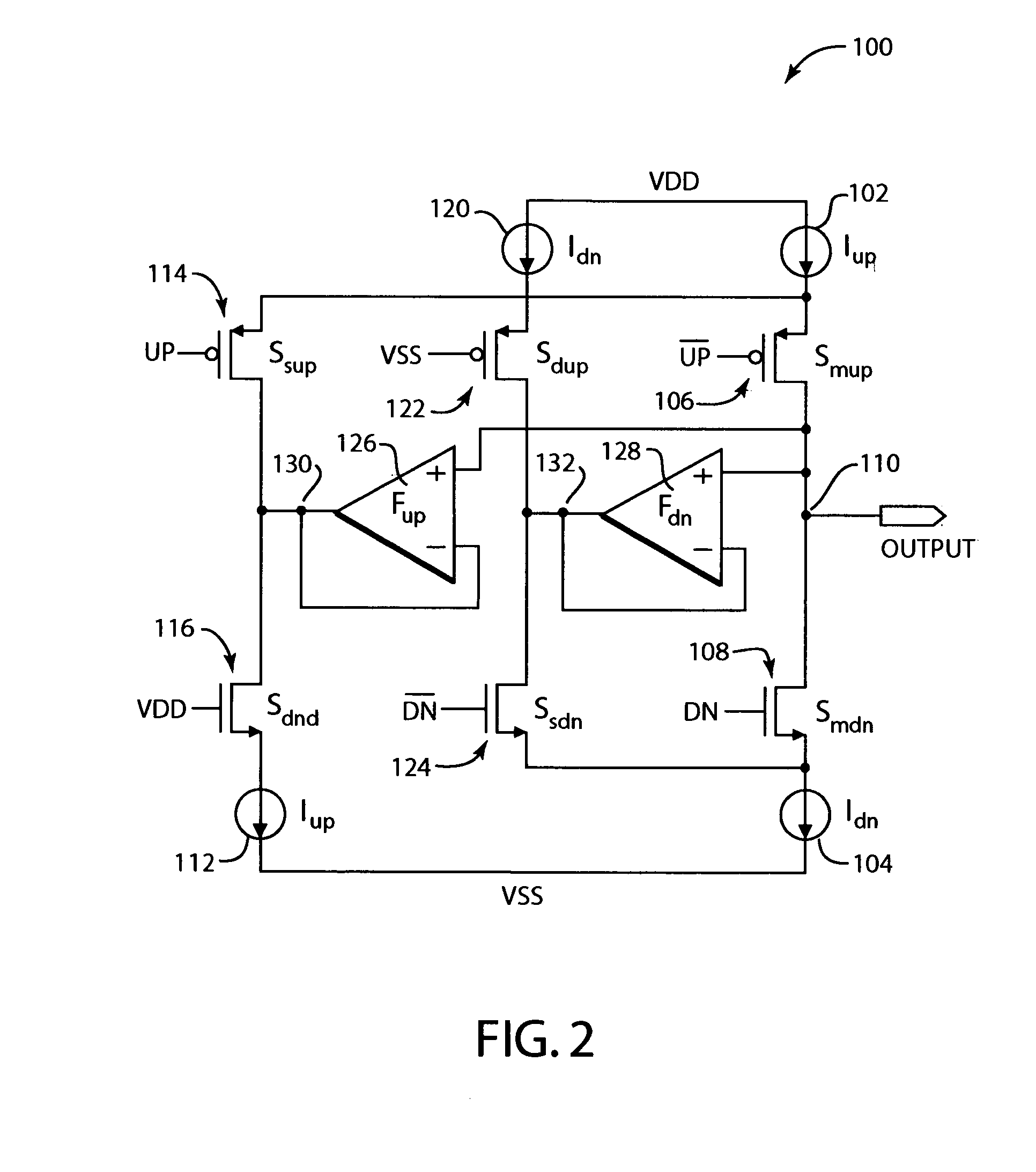
[0012]The present invention provides a charge pump that can provide output substantially free of glitches and DC offset. Multiple current steer branches, multiple current sources, and buffers in various embodiments allow minimization of timing mismatch and glitch errors from the charge pump. Furthermore a replica portion of the circuit can allow minimization of current mismatch in a wider range of output voltage.

Problems solved by technology

The source and sink current waveforms of a hardware implementation of a charge pump exhibit offset and glitch errors which cause the sink and source current waveforms to be asymmetrical.
The asymmetry results in residual charge being left in the loop filter, producing a non-smooth control voltage and spur frequency tones in the output of the VCO.
However, timing mismatch that occurs in the switches of these prior charge pump circuits causes the current source and / or current sink to easily turn off and produce large glitches in the output of the charge pump, thus producing a higher level of spurious emissions in the VCO output.
Furthermore, current amplitude mismatch of the current source and the current sink is exponentially increased at output voltages close to the supply voltages VDD and VSS, causing large spurious emissions at the VCO and effectively defining an output voltage range of the charge pump as the range where the spurious emissions are kept below the level of spurious emissions needed to comply with the requirements of particular communications standards.

Method used


Image

  • Current steering charge pump having three parallel current paths preventing the current sources and sinks to turn off and on
  • Current steering charge pump having three parallel current paths preventing the current sources and sinks to turn off and on
  • Current steering charge pump having three parallel current paths preventing the current sources and sinks to turn off and on

Examples


Embodiment Construction

[0016]The present invention relates to a current steering charge pump and method therefor. The following description is presented to enable one of ordinary skill in the art to make and use the invention and is provided in the context of a patent application and its requirements. Various modifications to the preferred embodiment and the generic principles and features described herein will be readily apparent to those skilled in the art. Thus, the present invention is not intended to be limited to the embodiments shown but is to be accorded the widest scope consistent with the principles and features described herein.

[0017]Embodiments and examples of the present invention are described below. While particular applications and methods are explained, it should be understood that the present invention can be used in a wide variety of other applications and with other techniques within the scope of the present invention.

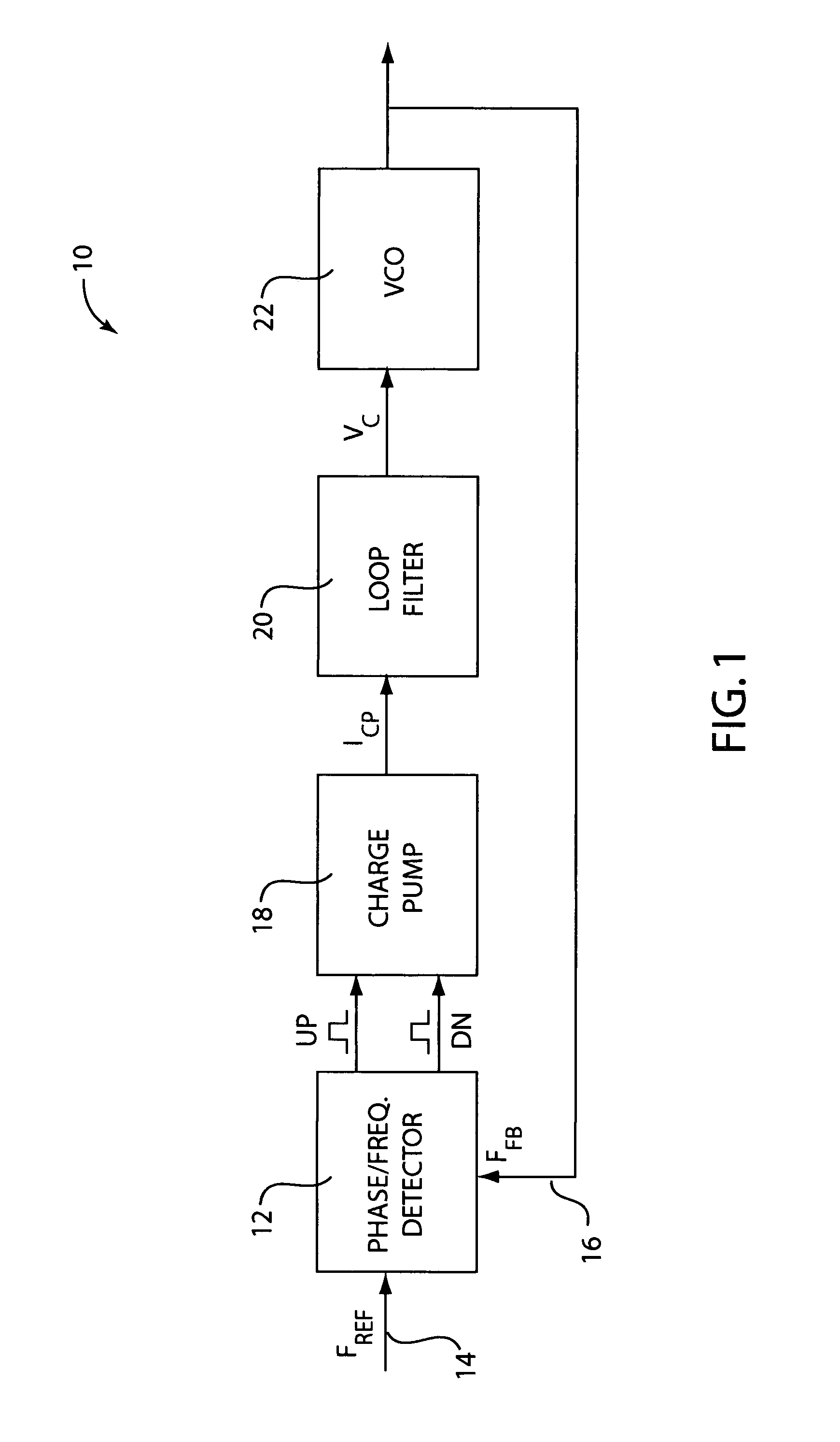
[0018]FIG. 1 is a block diagram illustrating one example of a charge...


PUM


Abstract

A current steering charge pump that receives control signals and sources and sinks current in response to the control signals. One embodiment includes a main current source, secondary current source, main current sink, and secondary current sink, and three different current paths between various of the current sources and current sinks. One embodiment includes buffers operative to maintain the node voltages of central nodes at the same voltage as the output node of the charge pump, where each buffer is coupled between two of the three current paths.

Description

CROSS-REFERENCE TO RELATED APPLICATIONS[0001]The present application claims the benefit of U.S. Provisional Patent Application No. 60 / 396,314, filed Jul. 17, 2002, entitled, “Current Steering Charge Pump with Double Current Sources Unity Gain Buffers and Replica,” which is incorporated herein by reference in its entirety.FIELD OF THE INVENTION[0002]The present invention relates to charge pump electrical circuits, and more particularly to charge pump circuits provided for phase-locked loop applications.BACKGROUND OF THE INVENTION[0003]Phase-locked loops (PLLs) are closed-loop phase control systems provided in electrical circuits and used in a wide variety of applications. A PLL compares the phase of an incoming reference clock signal to the phase of a periodic clock signal generated by an oscillator circuit and adjusts the periodic clock of the oscillator in both frequency and phase to the reference clock signal. PLLs are used in frequency synthesis, demodulation, clock recovery and ...

Claims


Application Information

Patent Timeline
IPC IPC(8): H03L7/093G05F3/02
CPCH03L7/0896
Inventor KOKOLAKIS, IOANNIS
Owner AVAGO TECH WIRELESS IP SINGAPORE PTE
Learn More