Signal converter having compensation unit

a compensation unit and signal converter technology, applied in the field of signal converters, can solve the problems of signal distortion disadvantageously reducing the frequency band of the communication system, single-ended signals are more affected by noise, etc., and achieve the effect of little signal distortion

Inactive Publication Date: 2010-01-12
SAMSUNG ELECTRONICS CO LTD
View PDF4 Cites 15 Cited by
  • Summary
  • Abstract
  • Description
  • Claims
  • Application Information

AI Technical Summary

Benefits of technology

[0010]A signal converter according to an aspect of the present invention includes a signal converting unit and a compensation unit. The signal converting unit generates intermediate differential signals at intermediate nodes in response to a single-ended signal. The compensation unit generates compensated differential signals at output nodes by minimizing phase and amplitude mismatch errors between the intermediate differential signals. The compensation unit includes a pair of transistors and a pair of capacitors configured in symmetry between the intermediate and output nodes.
[0017]In this manner, the compensated differential signals are ensured of having a substantially same amplitude and a complementary phase difference of 180° such that the RF receiver may operate with little signal distortion.

Problems solved by technology

The signal change of the single-ended signal in response to an input signal is slower than for differential signals, and the single-ended signal is more affected by noise.
Such signal distortion may disadvantageously reduce the frequency band of the communication system having the signal converter 5 of FIG. 1 according to the prior art.

Method used


Image

  • Signal converter having compensation unit
  • Signal converter having compensation unit
  • Signal converter having compensation unit

Examples


Embodiment Construction

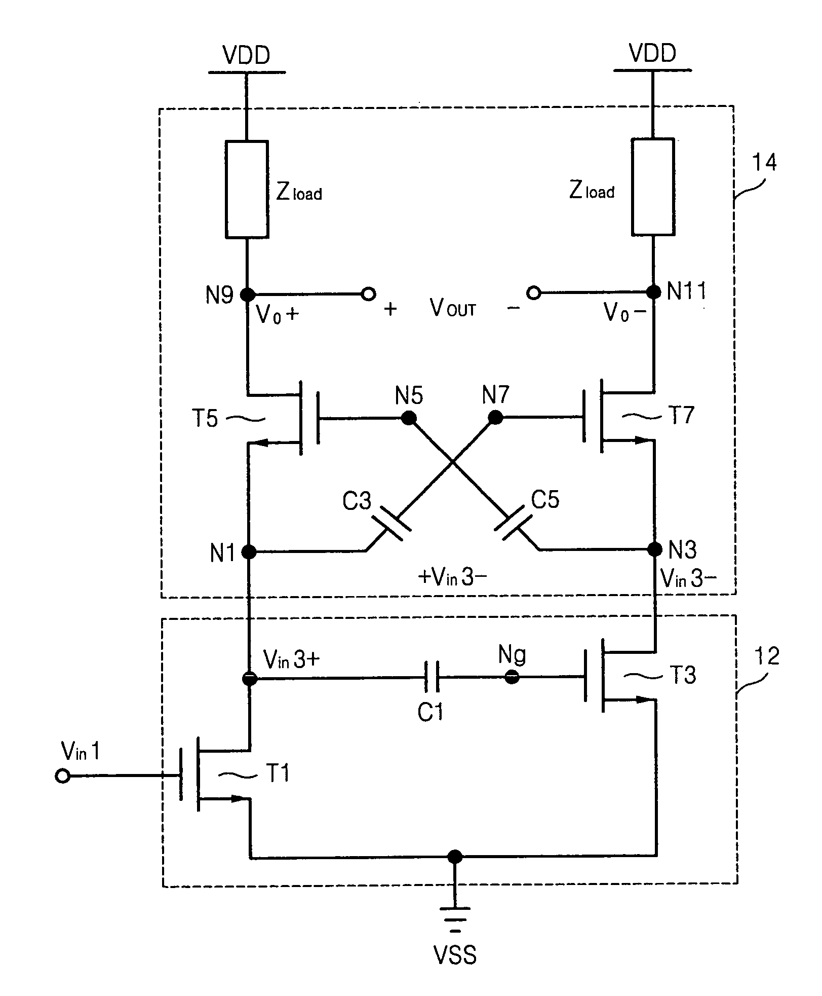
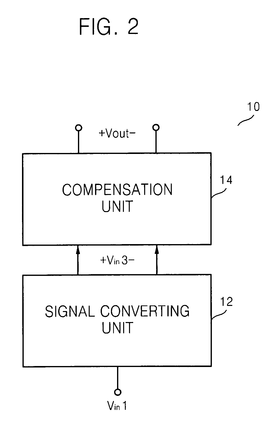
[0027]FIG. 2 is a block diagram of a signal converter 10, that may be embodied at a receiving end of a communication system for example, according to an embodiment of the present invention. The signal converter 10 includes a signal converting unit 12 and a compensation unit 14. FIG. 3 is a circuit diagram of the compensation unit 14 of FIG. 2. FIG. 4 is a circuit diagram of the signal converter 10 of FIG. 2.

[0028]The signal converting unit 12 generates intermediate differential signals Vin3+ and Vin3− in response to a single-ended signal Vin1. The signal converting unit 12 includes a first converting NMOSFET (N-channel metal oxide semiconductor field effect transistor) T1, a second converting NMOSFET (N-channel metal oxide semiconductor field effect transistor) T3, and a converting capacitor C1.

[0029]The first converting NMOSFET T1 has a drain coupled to a first intermediate node N1 and a source coupled to a low voltage supply VSS such as a ground voltage node. The first converting ...


PUM


Abstract

A signal converter includes a signal converting unit and a compensation unit. The signal converting unit generates intermediate differential signals at intermediate nodes in response to a single-ended signal. The compensation unit generates compensated differential signals at output nodes by minimizing phase and amplitude mismatch errors between the intermediate differential signals. The compensation unit includes a pair of transistors and a pair of capacitors configured in symmetry between the intermediate and output nodes. The signal converter of the present invention may be used to particular advantage in an RF receiver.

Description

BACKGROUND OF THE INVENTION[0001]This application claims priority under 35 USC § 119 to Korean Patent Application No. 2007-0013241, filed on Feb. 8, 2007 in the Korean Intellectual Property Office, the disclosure of which is incorporated herein in its entirety by reference.[0002]1. Field of the Invention[0003]The present invention relates generally to signal converters, and more particularly, to a signal converter having a compensation unit.[0004]2. Background of the Invention[0005]In general, a single-ended signal is measured with respect to a fixed potential, such as a ground voltage for example. The signal change of the single-ended signal in response to an input signal is slower than for differential signals, and the single-ended signal is more affected by noise. Accordingly, most circuits used in communication systems process differential signals with superior noise and impedance matching characteristics. In particular, the differential circuit structure is commonly adopted in ...

Claims


Application Information

Patent Timeline
Patent Type & Authority Patents(United States)
IPC IPC(8): H03F3/04
CPCH03F1/3211H03F3/193H03F3/45179H03F1/223H03F2203/45306H03F2203/45318H03F2200/451A47J37/0676H05B6/1209H05B6/129
Inventor MUN, HYUN-WONNAM, IL-KUKO, WON
Owner SAMSUNG ELECTRONICS CO LTD
Why Eureka
Try Eureka