Heating element condition monitor

a technology of condition monitor and heating element, which is applied in the direction of weather/light/corrosion resistance, instruments, transportation and packaging, etc., can solve the problems of heating element failure, serious consequences, and general deformation of heating elements with use, and achieve the effect of preventing the failure of heating elements

Inactive Publication Date: 2006-03-14
KANTHAL THERMAL PROCESS INC
View PDF10 Cites 20 Cited by
  • Summary
  • Abstract
  • Description
  • Claims
  • Application Information

AI Technical Summary

Benefits of technology

[0016]The resistance and the resistance ratio XR can be readily ascertained by way of various measurements, such as resistance or voltage and / or current measurements, a threshold value for a maximum acceptable deviation from a baseline value can be readily set, and a signal can be generated whenever that threshold is reached or exceeded. Thus, by way of a notification signal generated in such an instance, a heating element can be replaced before failure due to damage to the element's alloy that occurs as a result of thermal cycling degradation.

Problems solved by technology

Because of the thermal stresses caused by temperature cycling degradation attributed to changes in temperature from cold to hot and hot to cold, heating elements generally degrade with use and can eventually fail.
If the failure occurs unpredictably and at an inopportune time, serious consequences can result.
For example, the failure of a heating element can occur while devices such as a batch of semiconductors, are being heated in a furnace.
Consequences of the failure of a heating element used in such a process can include the loss of an entire batch of semiconductor product that is in the oven at the time of the heating element failure.
A failure can result in lost revenue, delayed shipments to customers, and a general inability to meet promised and expected yield rates for manufactured components.
However, it is often difficult to predict a life expectancy or reliability of heating elements.
Moreover, there can be a great deal of variability in the amount and quality of use of such heating elements, and differences in the quality of such items can be diverse as well.
In addition, other factors, such as intrinsic or elemental contamination of the materials, can also adversely affect the useful life of such a device.

Method used


Image

  • Heating element condition monitor
  • Heating element condition monitor
  • Heating element condition monitor

Examples


Embodiment Construction

[0040]Many different materials and alloy compositions exist that can be used to construct heating elements. The choice of the types of materials and alloy compositions used can depend upon the particular application with which the heating element is to be used, design requirements, economic considerations and other considerations. However, as will be appreciated by those skilled in the art, similar techniques to those described herein could be used with other alloys to achieve similar results.

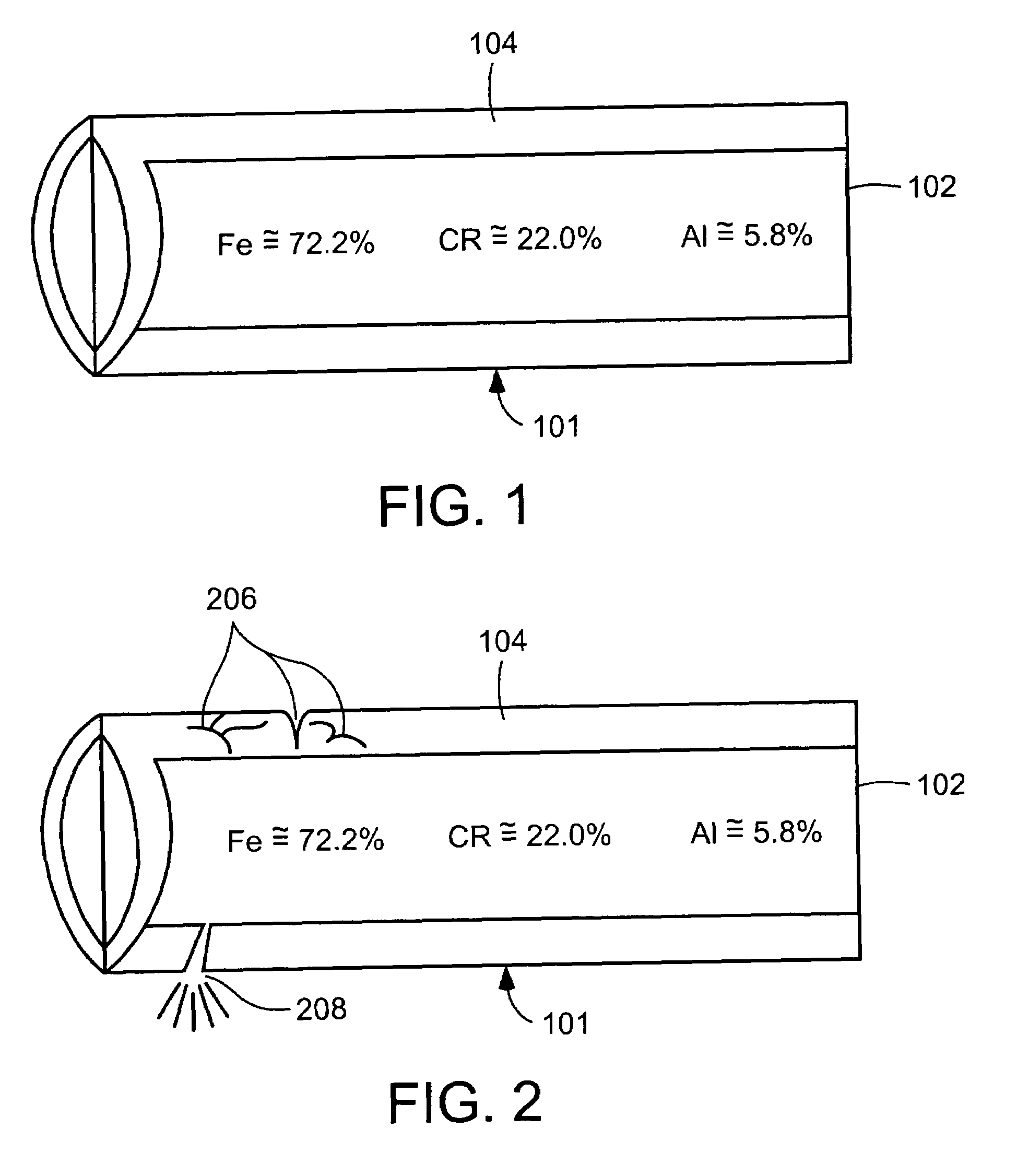
[0041]One type of wire alloy used to make up a heating element is an alloy consisting essentially of iron (Fe), chromium (Cr), and aluminum (Al), which is commonly referred to as an Fe / Cr / Al alloy. In the following description, for the purpose of illustration and not limitation, the present invention will be described in connection with an exemplary embodiment that uses the Fe / Cr / Al alloy to make a heating element. Those skilled in the art will recognize that other alloys and compositions can b...


PUM

PropertyMeasurementUnit
temperatureaaaaaaaaaa
thresholdaaaaaaaaaa
threshold levelaaaaaaaaaa

Abstract

A method for monitoring the condition of a heating element involving installing the heating element in a location and setting the initial composition Ci of the material as a reference baseline at an initial time Ti corresponding to said installation of the heating element. Data is then collected reflecting the subsequent composition Cs of the heating element material after a subsequent time Ts at the installed location and any change in the material composition of the heating element between Ti and Ts is monitored. An alarm is sent when the change reaches a threshold value indicating a possible failure condition. According to one embodiment, an impedance monitor is provided that calculates and compares impedance at the required levels of accuracy to determine changes in material composition. The impedance monitor, or portions thereof can be embedded within a microcontroller for increased portability and functionality.

Description

CROSS-REFERENCE TO RELATED APPLICATION[0001]This application is a continuation-in-part of and claims priority from U.S. nonprovisional patent application Ser. No. 10 / 196,160, filed Jul. 17, 2002, the contents of which are incorporated herein by reference.FIELD OF THE INVENTION[0002]The present invention relates to a method and apparatus for monitoring characteristics of a material to determine if that material has undergone a sufficient change in the monitored characteristics to indicate that a failure has occurred, or that an impending failure is about to occur. More particularly, the present invention relates to a method and apparatus for monitoring the physical and electrical characteristics of materials used as heating elements to indicate that there has been a failure or a partial failure of the heating elements, and / or to provide an indication of a heating element's condition and risk of pending failure.BACKGROUND OF THE INVENTION[0003]Many industrial applications and business...

Claims


Application Information

Patent Timeline
Patent Type & Authority Patents(United States)
IPC IPC(8): B60Q1/00G01N17/00H05B1/02
CPCG01N17/00H05B1/0291H05B1/0233
Inventor PECK, KEVIN B.JOHNSON, NOEL H.BERDNER, THOMAS J.
Owner KANTHAL THERMAL PROCESS INC
Why Eureka
Try Eureka