System architecture for high speed ray tracing

a system architecture and high-speed technology, applied in the field of generating images, can solve the problems of computationally expensive ray tracing process, achieve the effect of accelerating ray tracing performance, improving over time, and achieving the desired balance of cost and performan

Inactive Publication Date: 2006-03-14
ADVANCED MICRO DEVICES INC
View PDF4 Cites 141 Cited by
  • Summary
  • Abstract
  • Description
  • Claims
  • Application Information

AI Technical Summary

Benefits of technology

[0016]In another set of embodiments, a method for generating images of three-dimensional objects may be arranged as follows. A host program executing on a host computer may invoke the transfer of ray spawning code to a first processing unit. The first processing unit may perform a first set of computations to determine a ray tree and one or more light trees. The first set of computations may include one or more ray tracing operations and one or more ray spawning operations. The first processing unit performs the ray spawning operations by executing the ray spawning code. The first processor transfers the ray tree and the associated light trees to a second processing unit. The second processing unit performs a second set of computations on the ray tree and associated light trees to determine pixel color. The pixel color determines a pixel in an output image. The output image may be a frame in a real-time video stream.
[0017]In yet another set of embodiments, a system 3D image generation system may include one or more tracing processors and one or more shading processors. The tracing processors may be configure...

Problems solved by technology

Thus, ray tracing is a co...

Method used


Image

  • System architecture for high speed ray tracing
  • System architecture for high speed ray tracing
  • System architecture for high speed ray tracing

Examples


Embodiment Construction

1. General

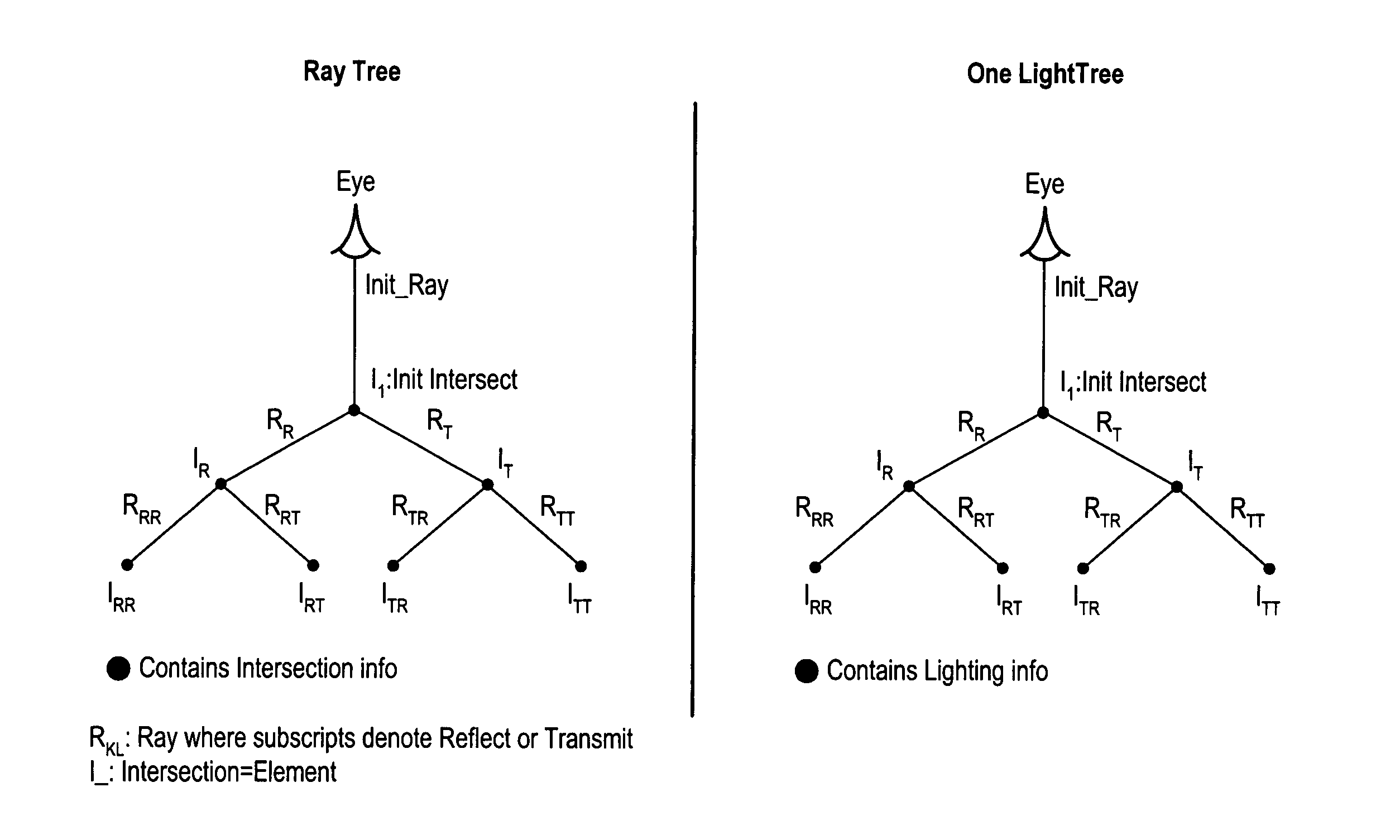
[0026]Ray tracing is a very compute intensive process. However, next generation central processing units (CPUs) and multi-processor (MP) systems will be more capable of delivering the computer power required for real time ray tracing (RTRT).

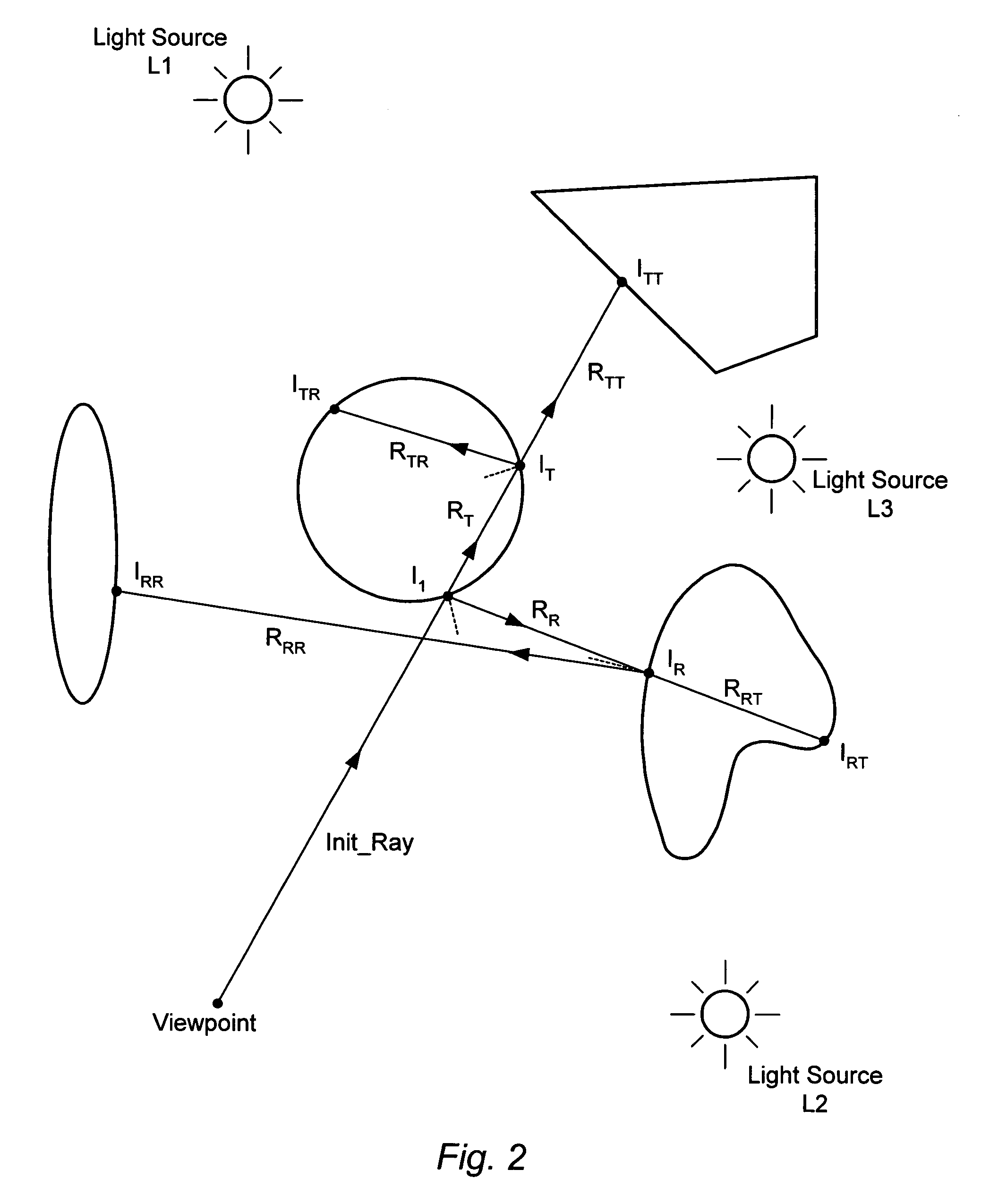
[0027]Ray tracing may be performed with different types of graphical elements such as triangles, spheres and parameterized surfaces (e.g. higher-order surfaces determined by control parameters). The following discussion focuses mostly on the use of triangles. However, the mechanisms described herein may be used with a variety of different element types.

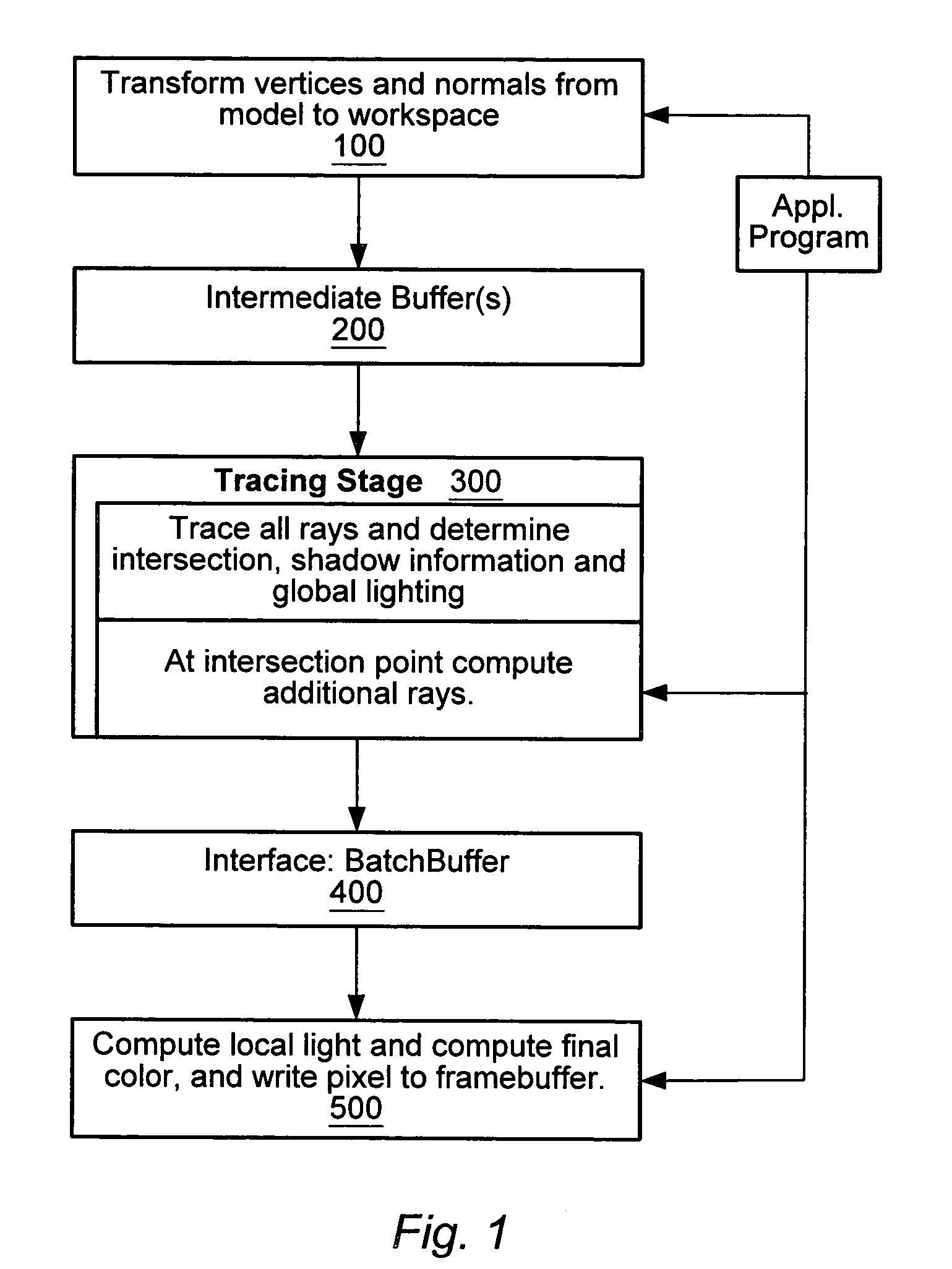
[0028]In one set of embodiments, a method for rendering three-dimensional objects (or N-dimensional objects where N is a positive integer) may be arranged as illustrated in FIG. 1.

[0029]Stage 1: Transformation[0030]In a transformation stage 100, vertices are transformed from model coordinates to world coordinates. Normal vectors are also transformed. Ray tracing is a global lighting model...


PUM


Abstract

A system and method for generating images of three-dimensional objects. The system includes one or more tracing processors, and one or more shading processors. Each of the tracing processors may be configured to (a) perform a first set of computations on a corresponding group of primary rays emanating from a viewpoint resulting in a ray tree and a set of one or more light trees for each primary ray of the corresponding group, (b) transfer the ray trees and associated light trees to one of the shading processors, and (c) repeat (a) and (b). Each of the shading processors may be configured to (d) receive ray trees and associated light trees from one of the tracing processors, (e) perform a second set of computations on the received ray trees and associated light trees to determine pixel color values, and (f) repeat (d) and (e) a plurality of times.

Description

BACKGROUND OF THE INVENTION[0001]1. Field of the Invention[0002]This invention relates to a system for generating images, and more particularly, to a ray-tracing system for generating images of three-dimension scenes in real-time.[0003]2. Description of the Related Art[0004]Ray tracing is the term used to describe a method for generating images of three-dimensional scenes. The method involves sending out a system of rays from a viewpoint in a world space. The world space may be populated by a collection of three-dimensional objects. Color values are computed for each of these rays, and the color values determine the pixels of a displayable image. To compute a color value (e.g. a RGB color vector) for a given ray may involve a set of computations such as the following. The point where the ray encounters its first intersection with an object may be determined. At this “primary” intersection point, a reflection ray and a transmission ray may be determined. (The transmission ray may be ...

Claims


Application Information

Patent Timeline
IPC IPC(8): G06T15/60
CPCG06T15/06G06T15/80G06T15/50
Inventor CHRISTIE, DAVID S.KRANICH, UWE
Owner ADVANCED MICRO DEVICES INC
Why Eureka
Try Eureka