Disk device and disk medium, in which a plurality of servo cylinders formed concentrically from the inner diametrical portion to the outer diametrical portion of at least one disk are divided into predetermined areas

Inactive Publication Date: 2006-03-14
TOSHIBA STORAGE DEVICE CORP
View PDF10 Cites 46 Cited by
  • Summary
  • Abstract
  • Description
  • Claims
  • Application Information

AI Technical Summary

Benefits of technology

[0036]In summary, according to the present invention, a plurality of servo cylinders are divided into several areas, and at the same time, a servo signal frequency is set for each of the areas in such a way that the recording density of the servo signals recorded from the inner diametrical portion to the outer diametrical portion of the disk is adjusted so as to allow the servo signal demodulation characteristic to be included in a relatively superior range. Thus, when the read/write head carries out the seek operation, the position of the read/write head at the time of reading the next servo signal pattern can be accurately estimated and the servo signals in the actual position of the read/write head can be accurately demodulated over the whole areas ranging from the inner diametrical portion to the outer diametrical portion of the disk.
[0037]Further, according to the present inv

Problems solved by technology

In the case in which the area actually reached by the read/write head and the area associated with the estimated position of the read/write head are different from each other, a servo signal frequency different from the servo signal frequency of the area actually reached by the read/write head is undesirably set for the read channel, thereby leading to the problem that it becomes impossible to demodulate the servo information.
Thus, the setting of the servo signal frequency of the read channel is different from the servo signal frequency of the servo signal actually read, and therefore,

Method used


Image

  • Disk device and disk medium, in which a plurality of servo cylinders formed concentrically from the inner diametrical portion to the outer diametrical portion of at least one disk are divided into predetermined areas
  • Disk device and disk medium, in which a plurality of servo cylinders formed concentrically from the inner diametrical portion to the outer diametrical portion of at least one disk are divided into predetermined areas
  • Disk device and disk medium, in which a plurality of servo cylinders formed concentrically from the inner diametrical portion to the outer diametrical portion of at least one disk are divided into predetermined areas

Examples


first embodiment

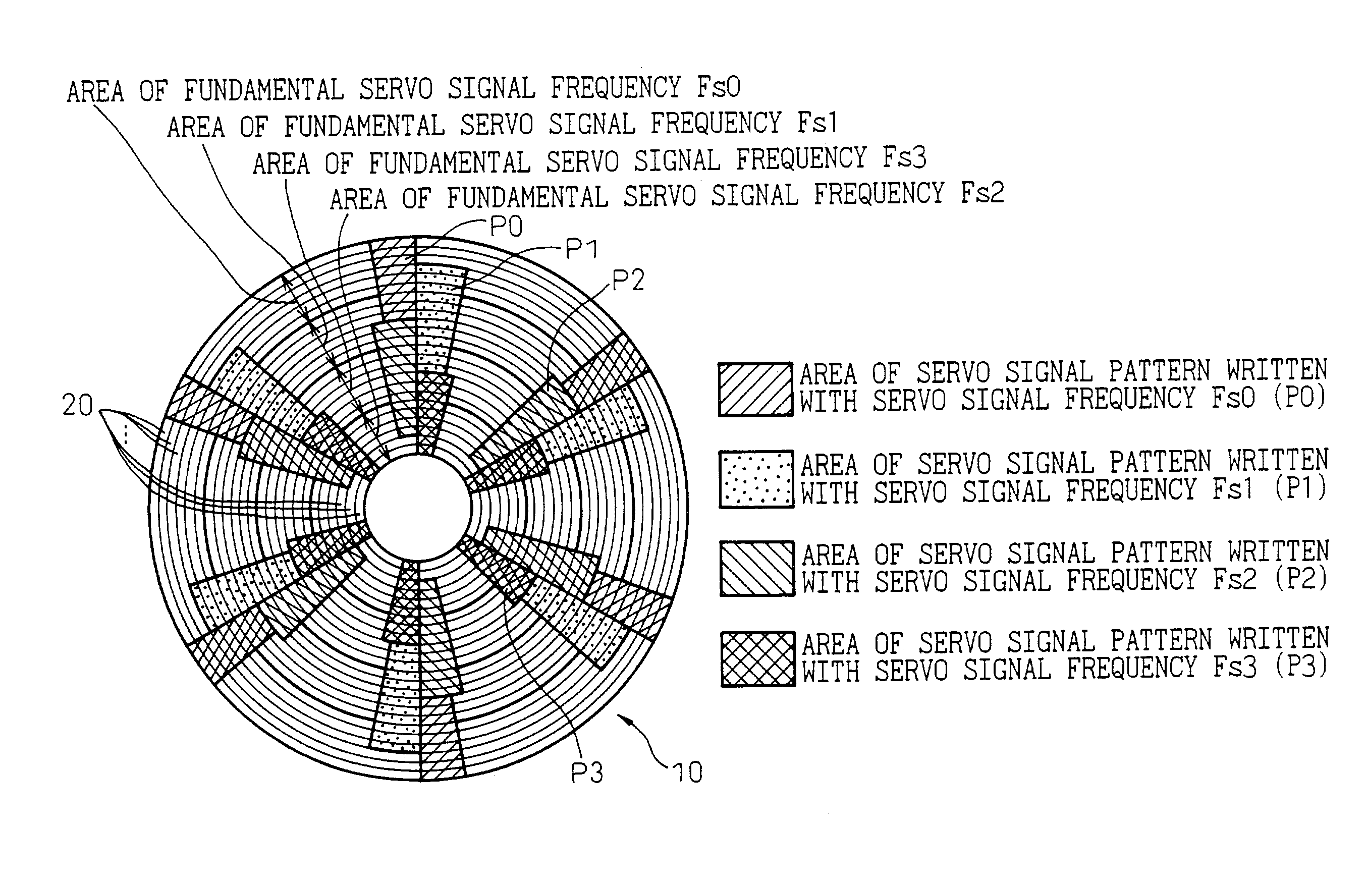
[0091]FIG. 10 is a diagram showing a layout of the servo signal patterns according to the present invention. The servo signal patterns formed on the servo cylinders 20 of a single disk 10 are typically illustrated.

[0092]According to the first embodiment shown in FIG. 10, the servo signal patterns are recorded with different recording density in the areas in which the servo signal is written on the disk surface. In the case under consideration, the areas of the servo cylinders 20 from the inner side to the outer side of the disk 10 are divided into two areas (P0, P1).

[0093]For each of the servo cylinder areas thus divided, different servo signal frequencies Fs0 and Fs1 are set, and a servo signal pattern corresponding to each servo signal frequency thus set is arranged in each area.

[0094]On the other hand, the servo signal frequencies are set so as to secure relatively satisfactory values of the error rate characteristic of the servo sync mark, the error rate characteristic of the gr...

second embodiment

[0113]FIG. 15 is a diagram showing a layout of the servo signal patterns according to the present invention. Also in this case, the servo signal patterns formed on the servo cylinders 20 of a single disk 10 are shown as a typical example.

[0114]In the second embodiment shown in FIG. 15, the servo signal patterns are recorded with different recording density in the area in which the servo signal is written on the disk surface. In this case, the portion from the inner side to the outer side of the disk 10 containing the servo cylinders 20 is divided into two areas (P0, P1).

[0115]For the servo cylinder areas thus divided, different servo signal frequencies Fs0 and Fs1 are set, respectively, so that the servo signal patterns of the set servo signal frequencies are arranged in the divided areas.

[0116]On the other hand, the servo signal frequencies are set so as to secure an error rate characteristic of the servo sync mark, the error rate characteristic of the gray code and the distributio...

third embodiment

[0142]FIG. 20 is a diagram showing a layout of the servo signal patterns according to the present invention. Also in this embodiment, the servo signal patterns formed on the servo cylinders 20 of a single disk 10 are shown as a typical example.

[0143]According to the third embodiment shown in FIG. 20, the servo signal patterns on the disk are recorded with different recording density in the area on the disk surface in which the servo signals are written. In this case, the areas of the servo cylinders 20 from the inner side to the outer side of the disk 10 are divided into several areas (P0 and P1, for example).

[0144]Different servo signal frequencies Fs0 and Fs1 are set for different areas of the servo cylinders thus divided, and the servo signal patterns corresponding to the servo signal frequencies thus set are arranged in the respective areas.

[0145]On the other hand, the servo signal frequencies are set so as to secure relatively satisfactory values of the error rate characteristi...


PUM


Abstract

A disk device and a disk medium are disclosed in which a plurality of servo cylinders on the surface of at least one disk are divided into several areas, and a different servo signal frequency is set and recorded for each of the areas. The servo cylinders are divided into predetermined areas, and a different servo signal frequency for each of the areas is set so that the recording density of the servo signal recorded in the disk can be set so as to allow the servo signal demodulation characteristic to be included in a relatively superior range. In the disk device, the boundary between the area of a first servo signal frequency and the area of a second servo signal frequency adjoining the first servo signal frequency area is preferably formed with an area in which a servo signal pattern written with the first servo signal frequency and a servo signal pattern written with the second servo signal frequency are arranged on the same servo cylinders.

Description

BACKGROUND OF THE INVENTION[0001]1. Field of the Invention[0002]The present invention relates to a disk device, and a disk medium, in which a plurality of servo cylinders formed concentrically from the inner diametrical portion to the outer diametrical portion of at least one disk, such as a magnetic disk, are divided into several areas, and a different servo signal frequency is set for each of these areas and recorded in advance.[0003]A disk rotatably set on a disk device, such as a magnetic disk device, may be removable from the disk device as in the case in which it is used as a single sheet of a disk of servo track writer (STW). In such a case, the disk may be shipped independently with servo signal patterns written in the servo cylinders. This disk (or a plurality of disks) is generally called “a disk medium” (or “disk media”).[0004]2. Description of the Related Art[0005]In order to facilitate the understanding of the problems of a disk device with servo signal patterns arrange...

Claims


Application Information

Patent Timeline
IPC IPC(8): G11B5/09G11B5/596G11B21/10
CPCG11B21/106G11B5/59633G11B5/596
Inventor ASHIKAGA, HIROSHISUZUKI, NOBUYUKI
Owner TOSHIBA STORAGE DEVICE CORP
Why Eureka
Try Eureka