Wafer edge inspection data gathering

a technology of wafer edge and data gathering, which is applied in the direction of mechanical roughness/irregularity measurement, semiconductor/solid-state device testing/measurement, instruments, etc., can solve the problems of too time-consuming and unreliable to adequately address the problem of wafer edge defects, and achieve the effect of efficient operation, quick location or identification

Inactive Publication Date: 2006-03-14
BELL SEMICON LLC
View PDF5 Cites 16 Cited by
  • Summary
  • Abstract
  • Description
  • Claims
  • Application Information

AI Technical Summary

Benefits of technology

[0012]Accordingly, the present invention preferably involves methods for gathering semiconductor wafer edge inspection data and systems or apparatuses for automated inspection of the semiconductor wafer edge. Generally, one or more points of interest on the edge of the wafer are supplied to a review tool, which is instructed to capture images at those points on the wafer edge. According to some particular embodiments of the present invention, the points of interest are supplied in automatic succession to the review tool, so the images at each of the points of interest may be captured rapidly and stored automatically. The speed of data gathering thus enabled allows for a much for efficient operation than the manual procedures described in the background.
[0013]Additionally, according to certain embodiments, the captured images are preferably automatically correlated with the points of interest at which the images were taken. Thus, the captured images can be quickly located or identified, without resorting to handwritten notes in a lab notebook.
[0015]According to other embodiments, the captured images are correlated with “context information” that preferably identifies the wafer from which the images were taken. Additional embodiments preferably include in the context information an identification of the fabrication process step performed on the wafer prior to capturing the images or gathering the inspection data. Additionally, the context information may preferably be computer-searchable, so that future data analysis may quickly search through the stored images captured from the same wafer after different fabrication process steps or captured from different wafers after the same process step. With this capability, an improved wafer edge inspection technique, such as the one described in the aforementioned patent application, may have highly efficient data searching, managing and analyzing features that are unavailable with the limited capabilities of the inspection techniques described in the background.

Problems solved by technology

It was realized that defects at the edge of a wafer, though they may be far from most of the IC's on the surface of the wafer, frequently cause problems in the fabrication of the IC's.
Therefore, a need has been recognized for an improved wafer edge inspection technique that goes beyond the limited capabilities of the inspection techniques described above, which have proven to be too time-consuming and unreliable to adequately address the problem of wafer edge defects during the over-all fabrication process.

Method used


Image

  • Wafer edge inspection data gathering
  • Wafer edge inspection data gathering
  • Wafer edge inspection data gathering

Examples


Embodiment Construction

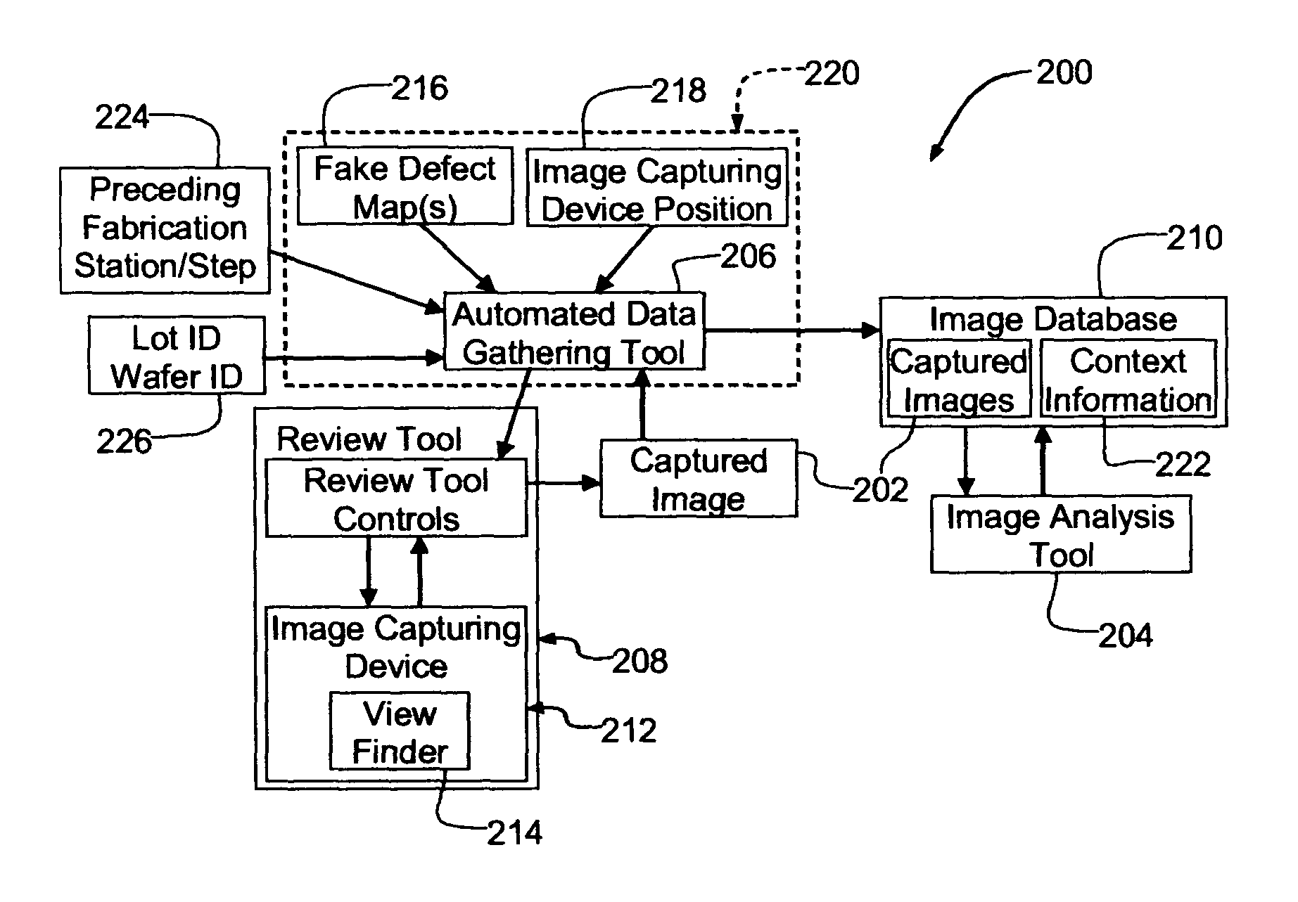
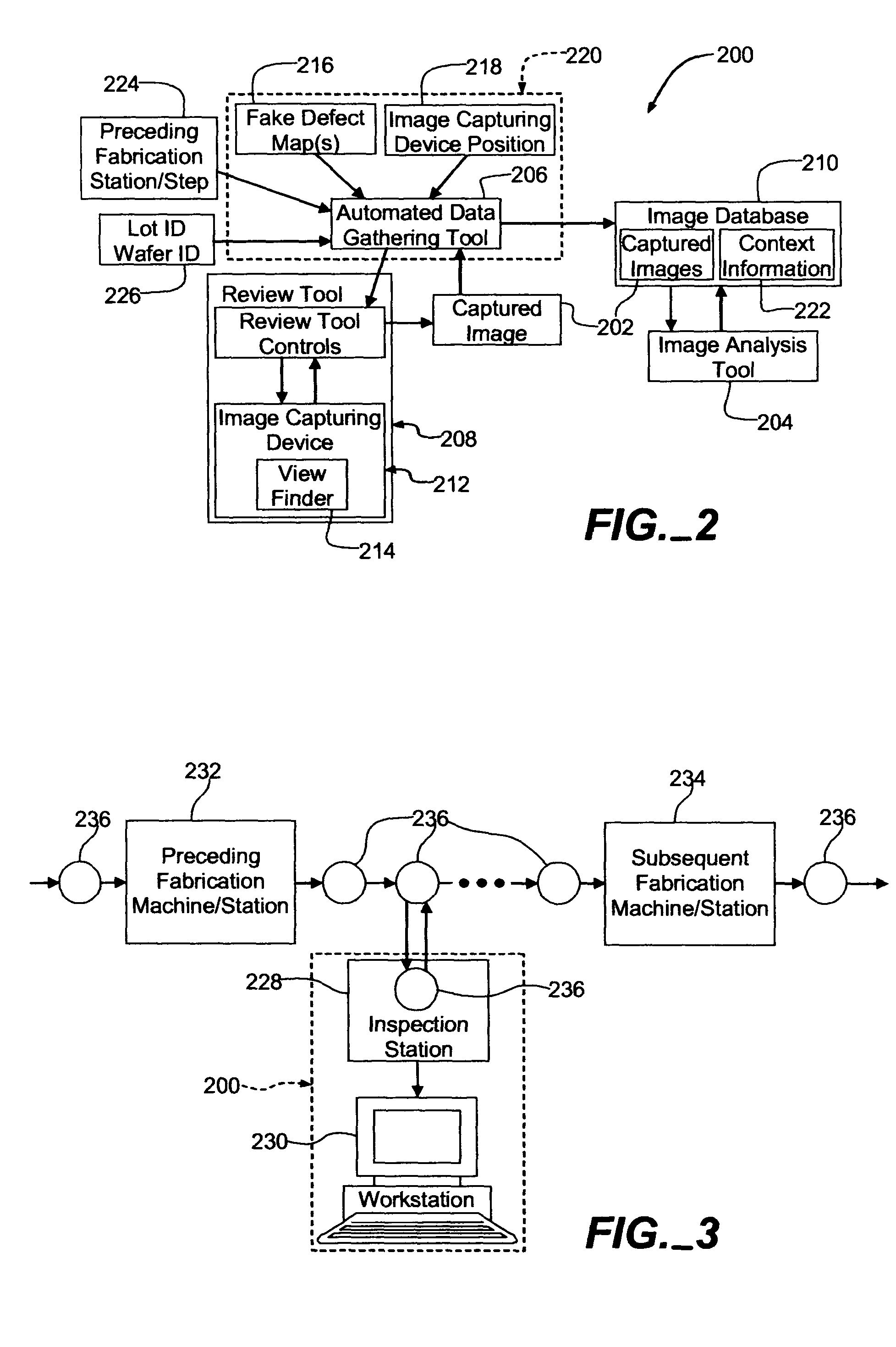
[0025]An exemplary wafer edge inspection system 200, as shown in FIG. 2, generally captures images 202 of the edge of a wafer (not shown), such as a semiconductor wafer used in the fabrication of integrated circuits, for detailed computer analysis thereof by an image analysis tool 204. The image analysis tool 204 generally analyzes the captured images 202 as described in the aforementioned patent application.

[0026]In addition to the image analysis tool 204, the wafer edge inspection system 200 generally includes an automated data gathering tool 206, a conventional review tool 208 and an image database 210. The automated data gathering tool 206, the review tool 208 and the image database 210 generally function together to automate the data capture, storage and management for the wafer edge inspection system 200.

[0027]The review tool 208 generally includes wafer inspection hardware, such as an image capturing device 212 having a view finder 214. The review tool 208 generally receives ...


PUM

PropertyMeasurementUnit
Edge Defect Inspectionaaaaaaaaaa
yield rateaaaaaaaaaa
sizeaaaaaaaaaa

Abstract

A wafer edge inspection method and apparatus include a review tool that captures images of the semiconductor wafer. According to various embodiments, the present invention also includes a map of points of interest proximate to the edge of the wafer, automatic image capturing at the points of interest, fake defect locations defining the points of interest, a database in which the images are stored and computer-searchable for detailed defect analysis, a software tool for controlling the method and apparatus and / or context information identifying the points of interest, the inspected wafer and / or the fabrication station / step preceding the inspection.

Description

CROSS-REFERENCE TO RELATED APPLICATION[0001]This invention is related to an invention for Wafer Edge Defect Inspection, described in U.S. patent application Ser. No. 10 / 628614, filed Jul. 28, 2003, which is assigned to the assignee of the present invention. The subject matter of this application is incorporated herein by this reference.FIELD OF THE INVENTION[0002]This invention relates to inspection of semiconductor wafers on which are formed integrated circuits (ICs). In particular, this invention relates to new and improved techniques for gathering data from inspection of the edges of the wafers.BACKGROUND OF THE INVENTION[0003]A significant trend throughout IC development has been to try to increase the “yield rate” of semiconductor fabrication systems. The yield rate refers to the percentage of usable IC's produced by a fabrication system compared to the total number attempted. Similarly, the yield rate may refer to the percentage of usable IC's obtained on average from a semico...

Claims


Application Information

Patent Timeline
Patent Type & Authority Patents(United States)
IPC IPC(8): G01N31/00G01B5/28G01R31/26H01L21/00G01N21/95G06F19/00H01L21/68
CPCG01N21/9503H01L21/681H01L21/67288
Inventor STRADER, NATHAN N.
Owner BELL SEMICON LLC
Why Eureka
Try Eureka