
Method of making self-piercing nuts

Active Publication Date: 2006-03-21
SHINJO SEISAKUSHOKK
View PDF30 Cites 13 Cited by
  • Summary
  • Abstract
  • Description
  • Claims
  • Application Information

AI Technical Summary

Benefits of technology

[0005]An object of the present invention made in view of the drawbacks inherent in the prior art methods is therefore to provide a novel method of mass-producing the rectangular type self-piercing nuts in such a manner that any conventional nut-former can be used to inexpensively form lateral grooves in the opposite side walls of a pilot portion of each nut.
[0007]Preferably, an upper and lower round recesses or countersinks may be formed centrally of the nut blank and simultaneously with the step of coining the nut blank. In this case, this coining step itself as well as, or rather, the later step of boring the rough hole will be facilitated to a considerable degree.

Problems solved by technology

However, round starting rods have not necessarily been easy to roll or draw through a die in order to form such profiled elongate material.
Thus, manufacture of the self-piercing nuts according to the prior art method has been much more expensive than in case of producing ordinary nuts.

Method used


Image

  • Method of making self-piercing nuts
  • Method of making self-piercing nuts
  • Method of making self-piercing nuts

Examples


Embodiment Construction

[0022]Now an embodiment of the present invention will be described referring to the accompanying drawings, in which FIGS. 1(a) to 5(b) show a nut bank that is being processed in an ordinary and widely used nut-former at the sequential steps for manufacturing a self-piercing nut.

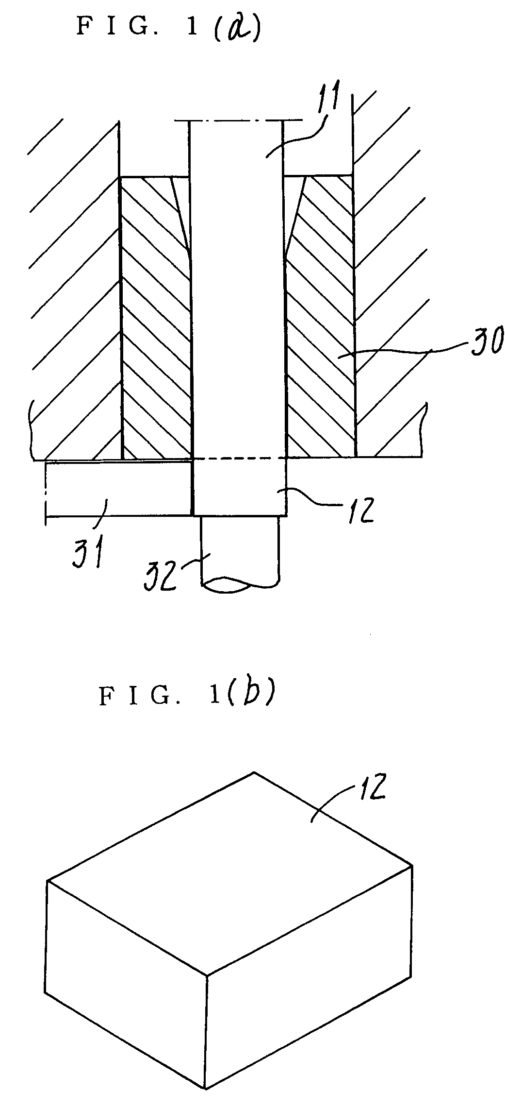
[0023]FIGS. 1(a) and 1(b) show the first step of preparing a raw nut blank 12 of a required cut length corresponding to a self-piercing nut. A low-carbon steel rod 11 usually forming a coiled spring is placed in this case in and through a quill 30, and then a knife 31 severs from the rod 11 the blank 12 of said length projected from the quill. The reference numeral 32 denotes a stopper for determination of a distance equal to the given length.

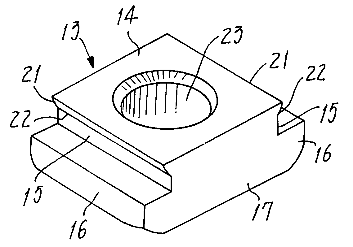
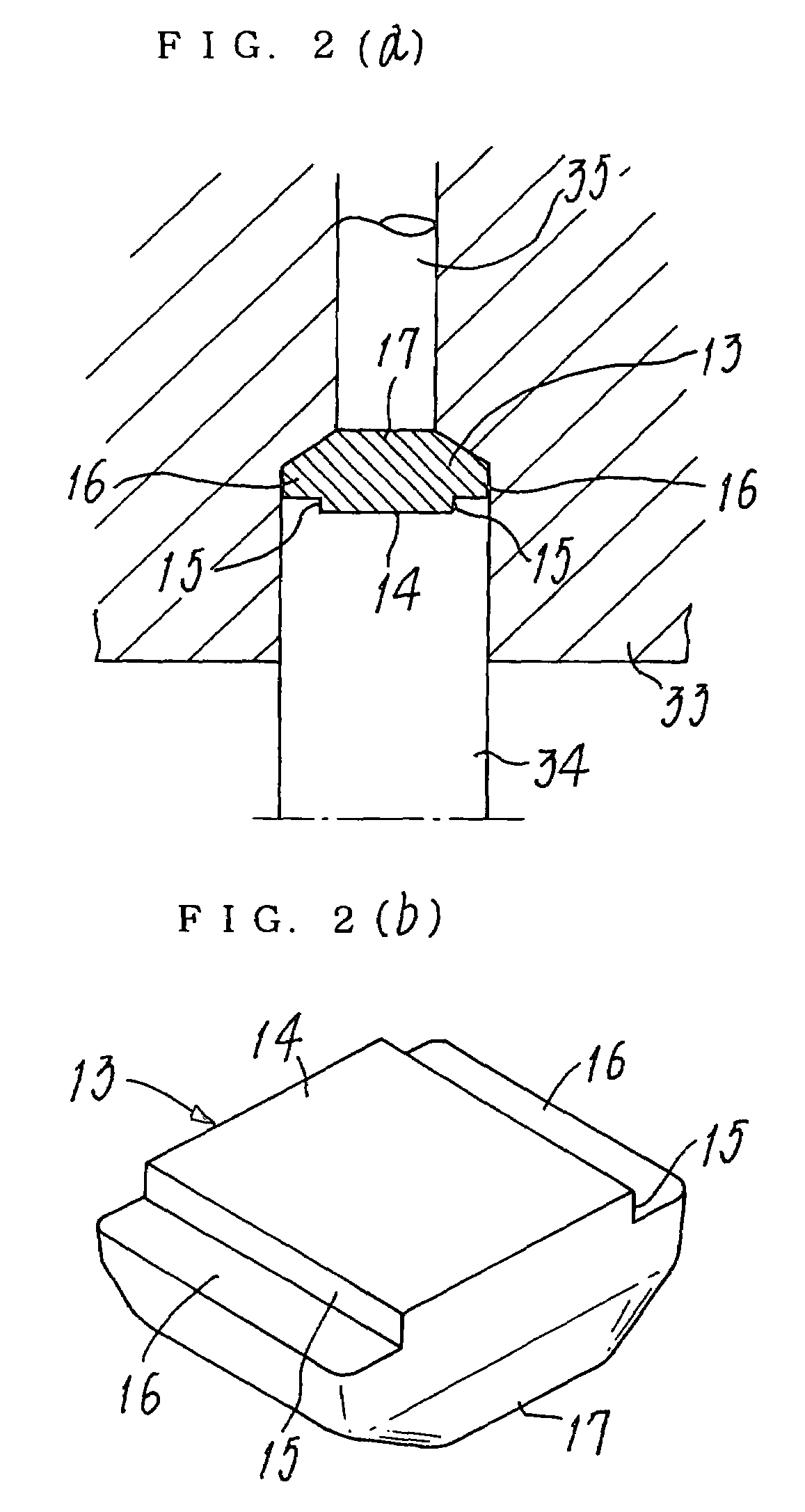
[0024]FIGS. 2(a) and 2(b) show the second step of preliminarily swaging the raw nut blank 12 within a closed mold. A punch 34 of this mold has pressed this blank into a die 33, so as to give an unfinished nut blank 13. The thus swaged nut blank 13 will have a rough pilot...


PUM


Abstract

A raw parallelepiped metal piece is pressed into a closed mold to provide a nut blank that has a generally square pilot portion (14) for piercing a metal panel, the nut blank having a pair of flanges (16) that continue from opposite side walls (15) of the pilot portion. Then, the nut blank is coined to form ridges (20) extending along and integral with opposite upper edges of the side walls (15), before pressed within an open mold so that the ridges are swaged out sideways to form shoulders (21). A lateral groove (22) is defined between below each shoulder and in the side wall. A rough bore (23) will be formed axially through the pilot portion (14), before tapped to have a female thread (24) in the inner periphery of the bore.

Description

FIELD OF THE INVENTION[0001]The present invention relates to a method of making the so-called self-piercing nuts, wherein each of them has a pilot portion formed in and protruding from one of opposite end faces so as to surround a threaded bore penetrating a nut body. This body of the self-piercing nut has to serve per se as a punch for punching a hole through a metal panel in such a manner that opposite regions of a closed and generally rectangular edge of the hole are caulked to bite and fix the nut in position. Such a fixing process takes place instantly and in an automatically clicking manner.PRIOR ART[0002]Some types of self-piercing nuts are known in the art, and one example is shown in the U.S. Pat. No. 2,707,372 or ibid. No. 3,152,628. Those nuts are of a rectangular configuration (usually called “universal type”), and they have the most basic structure adapted for use on a large scale in manufacture of automobile car parts.[0003]FIGS. 7(a)and 7(b)illustrate the self-piercin...

Claims


Application Information

Patent Timeline
IPC IPC(8): B23P13/04B21K1/70
CPCB21K1/702Y10T29/49995Y10T29/49837Y10T29/49996
Inventor SHINJO, TADASHI
Owner SHINJO SEISAKUSHOKK
Features
  • Generate Ideas
  • Intellectual Property
  • Life Sciences
  • Materials
  • Tech Scout
  • Unparalleled Data Quality
  • Higher Quality Content
  • 60% Fewer Hallucinations
Learn More