Composite slab and joist assembly and method of manufacture thereof

a technology of composite slabs and joists, which is applied in the direction of joists, girders, trusses, etc., can solve the problems of limited access, difficult to weld structural angles, and limit the surface area available for welded connections, so as to improve structural integrity and improve the bonding of joists

Inactive Publication Date: 2006-03-21
SWIRNOW R & D
View PDF10 Cites 42 Cited by
  • Summary
  • Abstract
  • Description
  • Claims
  • Application Information

AI Technical Summary

Benefits of technology

[0029]The present invention is an improvement over prior art steel and concrete structures that have at least one pair of spaced-apart parallel joists, each of which includes at least a top chord, and where a wooden form is mounted between the respective top chords of the pair of joists for subsequently pouring a concrete slab therebetween, the wooden form subsequently being removed once the concrete has cured. In this improvement, the top chord of each joist has two complementary structural angles including first and second structural angles secured to each other. The first structural angle has an upwardly-extending leg and a horizontally-extending leg forming a first corner therebetween. The second structural angle has a downwardly-extending leg and a horizontally-extending leg forming a second corner therebetween. The horizontally-extending leg of the second structural angle extends in a direction oppositely of the horizontally-extending leg of the first structural angle. The first and second angle members are disposed such that their respective corners substantially engage or confront one another, thereby forming in cross-section a substantially “plus” symbol. A panel is permanently mounted horizontally between the pair of joists, thereby providing a concrete form, and concrete poured over the panel to form a slab. Thus, the present invention eliminates the necessity of constructing, and subsequently removing, a wooden form between the pair of joists.
[0030]The above-described improvement has additional aspects. For example, the panel may be a metal corrugated panel. Also, the upwardly-extending legs of the first structural angles may have alternately-disposed protrusions and indentations, which improve the bonding of the joists to the concrete slab. Additionally, each joist may include a bottom chord connected to the top chord by a web. Further, the web may include compression and tension members, each of which has an upper end and a lower end, the respective upper ends being connected to the downwardly-extending leg of the second structural angle, which provides improved structural integrity. The structure may include girders, beams, or walls on which the joists are supported, and wherein a reinforcing shoe is disposed at the respective ends of the joists and contact the girders, beams, or walls of the structure. Also, the bottom chord may include a pair of complementary structural angles having respective upwardly-extending spaced-apart legs for securing therebetween the lower ends of the respective compression and tension members of the web.

Problems solved by technology

Accordingly, such a configuration limits the surface area available for the welded connection.
However, for welding structural angle 240 to web 224, access is limited due to the positioning of structural element 216.
Consequently, it is difficult to weld structural angle 240 sufficiently to develop its working capacity beyond supporting a deck panel 236.

Method used


Image

  • Composite slab and joist assembly and method of manufacture thereof
  • Composite slab and joist assembly and method of manufacture thereof
  • Composite slab and joist assembly and method of manufacture thereof

Examples


Embodiment Construction

[0054]The invention summarized above and defined by the claims below may be better understood by referring to the present detailed description, which should be read with reference to the accompanying drawings. This detailed description presents preferred embodiments of the present invention. This description is not intended to limit the scope of the claims but instead to provide examples of the invention.

[0055]Described first are preferred embodiments of joists configured in accordance with the present invention. Also described are implementations for manufacturing the joists. Then described is a preferred embodiment of a composite slab and joist assembly in accordance with the invention.

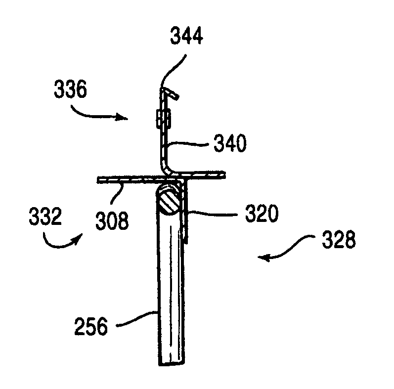
[0056]As illustrated in FIG. 6, a preferred embodiment of a joist 244 configured in accordance with the present invention includes a bottom chord 248, a top chord 252, and in open web 256 affixed therebetween. Web 256 of this embodiment is formed of a series of adjacent triangulating compression and...


PUM


Abstract

A composite slab and joist assembly includes a joist, at least one deck panel on the joist, slab reinforcement above the joist and dock panel, and a slab of concrete formed on the deck panel and joist such that the slab encloses the slab reinforcement and a top portion of the joist. The joist includes a bottom chord, a top chord, and a web affixed therebetween. The top chord has first and second structural angles. The first structural angle has in cross-section a horizontally-extending leg and an upwardly-extending leg meeting at a corner. The second structural angle has in cross-section a horizontally-extending leg and a downwardly-extending leg meeting at a corner. The upper portion of the web is joined to the second structural angle against the downwardly-extending leg.

Description

RELATED APPLICATION[0001]This application claims priority under 35 U.S.C. § 119(e) to U.S. Provisional Application No. 60 / 400,205, filed Jul. 31, 2002, which is hereby incorporated by reference in its entirety.FIELD OF THE INVENTION[0002]The present invention relates to composite structure construction, and more particularly to a composite slab and joist assembly.BACKGROUND[0003]The prior art is replete with examples of composite structure constructions employing composite slab and joist assemblies. In many of these examples, the slabs of concrete are positioned on the joists, and, during construction, to support the newly-poured unset concrete that will become parts of the slabs, forms for the concrete are mounted between adjacent joists of the assemblies.[0004]Butts et al. (U.S. Pat. No. 3,845,594) discloses an example of a composite slab and joist assembly in which the forms for the unset concrete are made of plywood. After the concrete hardens, the plywood is removed and reused....

Claims


Application Information

Patent Timeline
Patent Type & Authority Patents(United States)
IPC IPC(8): E04C3/30
CPCE04B5/29E04C5/065E04C3/294E04B5/40
Inventor BOELLNER, RUSSELL A.SWIRNOW, DAVID E.
Owner SWIRNOW R & D
Why Eureka
Try Eureka