System and method for confining an object to a region of fluid flow having a stagnation point

a technology of fluid flow and object, which is applied in the direction of liquid/fluent solid measurement, laboratory glassware, instruments, etc., can solve the problems of affecting the observation of particle size, environmental conditions surrounding the sample under investigation, and limitations of the bentley/leal devi

Inactive Publication Date: 2006-03-21
THE BOARD OF TRUSTEES OF THE LELAND STANFORD JUNIOR UNIV
View PDF3 Cites 16 Cited by
  • Summary
  • Abstract
  • Description
  • Claims
  • Application Information

AI Technical Summary

Problems solved by technology

The Bentley / Leal device has drawbacks and limitations that are not insignificant.
For example, the operation of the device depends on a complicated computer-controlled system.
Additionally, the four, relatively large, rollers are moving parts within close proximity of the millimeter-size particle, thereby interfering with, for example, observation of the particle.
With this configuration, the environmental conditions surrounding the sample under investigation (such as the fluid type, ionic strength and / or type, pH, other additives such as specific enzymes, etc.) cannot be altered seamlessly or easily, because the Bentley / Leal device does not provide a means for introducing fluid into the closed bath of fluid.
Another drawback of the Bentley / Leal device is that it employs a relatively deep bath of fluid, resulting in a fluid flow that is non-planar, thereby causing the particle trapped by the flow to drift up and / or down, without leaving the stagnation “point” (or a locus of stagnation points).
More particularly, with an optional imaging device located directly above or below the Bentley / Leal four-roll mill device, the trapped particle may drift out of focus, especially during prolonged observation.

Method used


Image

  • System and method for confining an object to a region of fluid flow having a stagnation point
  • System and method for confining an object to a region of fluid flow having a stagnation point
  • System and method for confining an object to a region of fluid flow having a stagnation point

Examples


Embodiment Construction

[0021]To provide an overall understanding of the invention, certain illustrative practices and embodiments will now be described, including a system for confining an object to a region of a fluid in motion and a method for doing the same. However, it will be understood by one of ordinary skill in the art that the systems and methods described herein can be adapted and modified and applied in other applications, and that such other additions, modifications, and uses will not depart from the scope hereof.

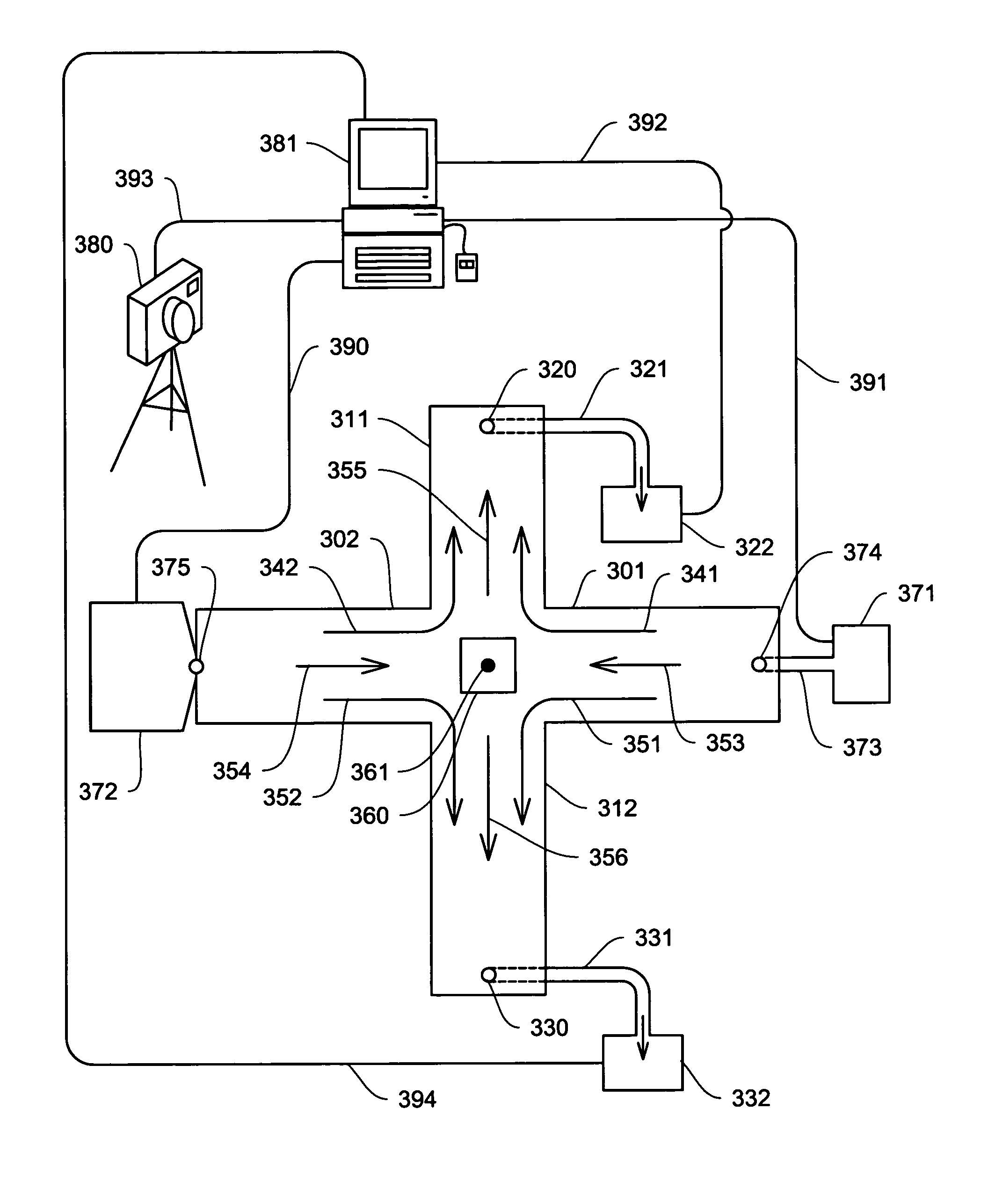
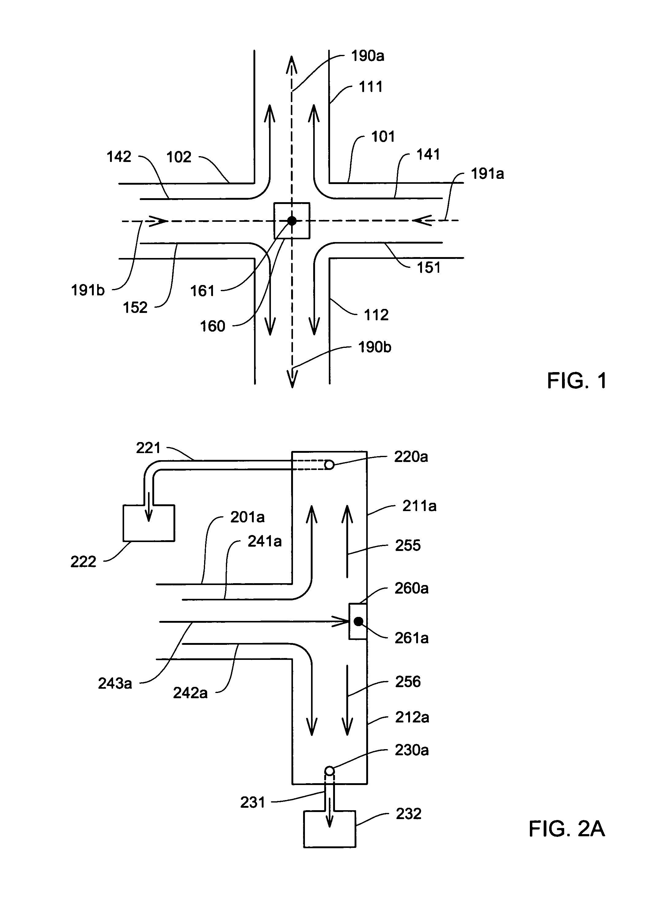
[0022]FIG. 1 depicts a top-view of a cross-shaped network of inlets and outlets representing an embodiment of the systems and methods described herein. A pressure-driven fluid flows along sample flow trajectories 141, 142, 151, and 152 toward, and past, stagnation region 160. Stagnation point 161 denotes the point of zero fluid velocity produced by the meeting of fluid flow in inlets 101 and 102.

[0023]In a pressure-driven flow, the fluid tends, on average, to flow from regions of high...


PUM


Abstract

A device for confining an object to a region proximate to a fluid flow stagnation point includes one or more inlets for carrying the fluid into the region, one or more outlets for carrying the fluid out of the region, and a controller, in fluidic communication with the inlets and outlets, for adjusting the motion of the fluid to produce a stagnation point in the region, thereby confining the object to the region. Applications include, for example, prolonged observation of the object, manipulation of the object, etc. The device optionally may employ a feedback control mechanism, a sensing apparatus (e.g., for imaging), and a storage medium for storing, and a computer for analyzing and manipulating, data acquired from observing the object. The invention further provides methods of using such a device and system in a number of fields, including biology, chemistry, physics, material science, and medical science.

Description

CROSS-REFERENCE TO RELATED APPLICATIONS[0001]This application incorporates by reference in entirety, and claims priority to and benefit of, U.S. Provisional Patent Application No. 60 / 498,875, filed on Aug. 29, 2003.GOVERNMENT SUPPORT[0002]Part of this work was supported by grants from the Center on Polymer Interfaces and Macromolecular Assemblies; the U.S. Air Force Office of Scientific Research; Office of Naval Research; NASA; Materials Research Science and Engineering Center; and the National Science Foundation (NSF). The U.S. Government has certain rights in this invention.BACKGROUND[0003]Fluid may be used to manipulate the movement of small particles. One method for controlling the location of a zero-velocity position in flow is described by Bentley and Leal (“A computer-controlled four-roll mill for investigations of particle and drop dynamics in two-dimensional linear shear flows”, J. Fluid Mech., v. 167, pp. 219–240, 1986). The Bentley / Leal device provides four rollers, which...

Claims


Application Information

Patent Timeline
Patent Type & Authority Patents(United States)
IPC IPC(8): G01F1/00G01Q60/00
CPCB01L3/50273B01L3/502761B01L2200/0668B01L2400/086B01L2300/1827B01L2400/082B01L2200/10
Inventor SCHROEDER, CHARLES M.SHAQFEH, ERIC S. G.BABCOCK, HAZEN P.CHU, STEVEN
Owner THE BOARD OF TRUSTEES OF THE LELAND STANFORD JUNIOR UNIV
Why Eureka
Try Eureka