Engine air brake device for a 4-stroke reciprocating piston internal combustion engine

a technology of reciprocating pistons and air brake devices, which is applied in the direction of machines/engines, mechanical equipment, output power, etc., can solve the problems of more than two valves and no solution suggested, and achieve the effect of high engine braking output and low cos

Active Publication Date: 2006-03-21
MAN TRUCK & BUS AG
View PDF6 Cites 55 Cited by
  • Summary
  • Abstract
  • Description
  • Claims
  • Application Information

AI Technical Summary

Benefits of technology

[0004]This object is inventively realized by an engine air brake device characterized by an engine-internal braking device that is associated with only one of the two exhaust valves for each cylinder, the other exhaust valve becoming active conventionally, wherein the engine-internal braking device has a control piston on which the stem of the exhaust valve is supported; the control piston is movably guided axially in a blind bore of the valve bridge and is pressed in the direction of the exhaust stem from a control pressure chamber supplied with pressurized oil and possibly also by means of an additional control compression spring. Pressurized oil is supplied to the control pressure chamber via a valve-bridge-internal oil-supply duct which communicates with a rocker-arm-internal oil-supply duct and in which a check valve permitting passage only in the direction of the control pressure chamber is installed. A relief duct exits the control pressure chamber and emerges on the top side of the valve bridge; its outlet orifice can be closed by a brace doubling as a stop for the valve bridge and for relieving pressure from the control pressure chamber after the valve bridge and for relieving pressure from the control pressure chamber after the valve bridge has risen. Furthermore, the pre-tensioning force of the closing spring allocated to this exhaust valve is proportioned such that during engine deceleration, when the throttling device is in throttling position, an intermediate opening of the exhaust valve is effected because of the exhaust back pressure accumulated in the exhaust gas in conjunction with the pressure pulsations effective therein. In this intermediate opening it is possible to intervene with the engine-internal braking device during each 4-stroke engine cycle in a control-related automatic manner so that after the intermediate opening at the beginning of the 2nd stroke the exhaust valve, which is about to close, is intercepted by the approaching control piston charged with oil pressure, and possibly also by means of the control compression spring, is prevented from closing during the 2nd and 3rd strokes and is kept partially open until its camshaft-controlled opening at the beginning of the 4th stroke. The exhaust back pressure is highest when the throttling device is in closing position and can, if necessary, be lowered through the controlled and / or regulated opening of the throttling device to reduce the engine brake output and / or the temperature of engine-internal components to prevent them from overheating. The cross-section of the oil-supply ducts in the rocker arm and valve bridge and the pressure of the oil supplied to the control pressure chamber are adjusted to each other so that during the intermediate opening of the exhaust valve the control pressure chamber which enlarges in volume because of the departing control piston can be filled with pressurized oil almost completely and it is thus possible to keep the exhaust valve in the intercepted partial opening position at the end of the intermediate opening stroke.
[0007]It is apparent that the engine air brake device as per this invention can be realized with a few components which can be produced at low cost. Engine deceleration is effected in a control-related automatic manner without intervention from the outside only as a function of the exhaust back pressure in the shut-off exhaust train and provenly achieves a very high engine braking output.

Problems solved by technology

However, for engines with more than two valves no solution is suggested.

Method used


Image

  • Engine air brake device for a 4-stroke reciprocating piston internal combustion engine
  • Engine air brake device for a 4-stroke reciprocating piston internal combustion engine
  • Engine air brake device for a 4-stroke reciprocating piston internal combustion engine

Examples


Embodiment Construction

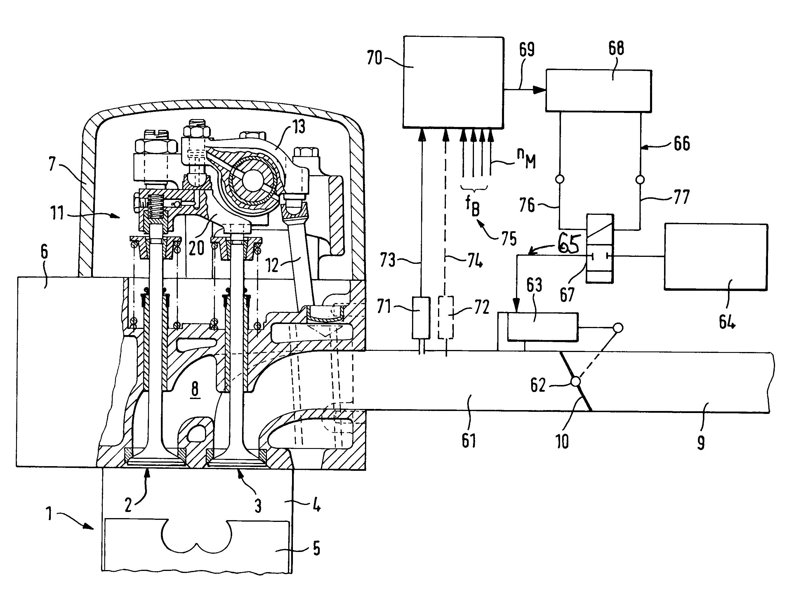
[0018]FIG. 1 shows a section of a 4-stroke reciprocating-piston internal combustion engine which has at least one intake valve (not shown) and two exhaust valves 2, 3 per cylinder. The combustion chamber of cylinder 1 is designated with 4, the piston working in cylinder 1 is designated with 5, a cylinder head with 6 and a cylinder cover with 7. The exhaust ports 8 of cylinder 1 discharge into one or several exhaust manifolds and, together with the latter, form a part of the exhaust train 9. In the exhaust train 9 a throttling device 10 is installed as close to the engine as possible. This device may be provided in the form of a butterfly valve or a flat-seat valve or a slide. In most cases a butterfly valve is used. The throttling device 10 together with its control and / or regulating organs (which will be described in greater detail later on) constitute a part of the engine air brake device as per this invention and serve for at least partially shutting off the exhaust train during ...


PUM


Abstract

An engine air brake device for a 4-stroke reciprocating-piston internal combustion engine is provided and has at least one intake valve and two exhaust valves per cylinder. The exhaust train incorporates a throttling device actuatable for engine deceleration so that an exhaust back pressure builds up in the accumulated exhaust gas upstream of the throttling device and becomes effective in conjunction with an engine-internal braking device associated to only one of the two exhaust valves for each cylinder, the other exhaust valve being controlled conventionally. The engine-internal braking device comprises a control piston installed in the valve bridge and pressed in the direction of the exhaust valve from a control pressure chamber supplied with pressurized oil and possibly also by means of an additional control compression spring.

Description

BACKGROUND OF THE INVENTION[0001]The invention concerns an engine air brake device for a 4-stroke reciprocating-piston internal combustion engine that has at least one intake valve per cylinder and two exhaust valves that are connected to an exhaust train and can be actuated via a valve bridge and a rocker arm that acts on the valve bridge and can be controlled by a camshaft either directly or indirectly via a push rod, each exhaust valve being biased in a closing direction by means of a closing spring, whereby a throttling device is installed in the exhaust train and can be actuated for engine deceleration such that an exhaust back pressure builds up in the accumulated exhaust gas upstream of the throttling device and becomes engine-internally active for engine deceleration in conjunction with a special braking device.[0002]The invention is based on EP 0736672 B1. This reveals a procedure for engine deceleration with a 4-stroke reciprocating piston internal combustion engine which ...

Claims


Application Information

Patent Timeline
Patent Type & Authority Patents(United States)
IPC IPC(8): F02D9/06F01L1/26F02D13/04F01N5/04F01L13/06F01N13/08F02D13/02
CPCF01L13/065F01L1/146F01L1/181F01L2820/02F01L1/26
Inventor RAMMER, FRANZRAAB, GOTTFRIEDLEITENMAYR, FRANZ
Owner MAN TRUCK & BUS AG
Why Eureka
Try Eureka