Apparatus and method for controlling fuel injection in internal combustion engine

a technology of internal combustion engine and fuel injection, which is applied in the direction of electric control, combustion engine, machine/engine, etc., can solve the problems of degrading the injection control performance, not meeting learning conditions,

Inactive Publication Date: 2006-03-21
TOYOTA JIDOSHA KK
View PDF10 Cites 29 Cited by
  • Summary
  • Abstract
  • Description
  • Claims
  • Application Information

AI Technical Summary

Benefits of technology

[0006]Accordingly, it is an objective of the present invention to provide an apparatus and method for controlling fuel injection in an internal combustion engine, which apparatus and method, based only on an injection mode in which fuel is supplied to a combustion chamber from at least two fuel injection valves, correct the fuel injection amount of at least one of the fuel injection valves and compensate for a deviation of the actual air-fuel ratio in relation to a target air-fuel ratio.

Problems solved by technology

However, in the injection modes in which fuel is supplied to each combustion chamber by using either one of the corresponding in-cylinder injector and port injector, learning conditions sometimes are not met.
This may degrade the injection control performance.

Method used


Image

  • Apparatus and method for controlling fuel injection in internal combustion engine
  • Apparatus and method for controlling fuel injection in internal combustion engine
  • Apparatus and method for controlling fuel injection in internal combustion engine

Examples


Embodiment Construction

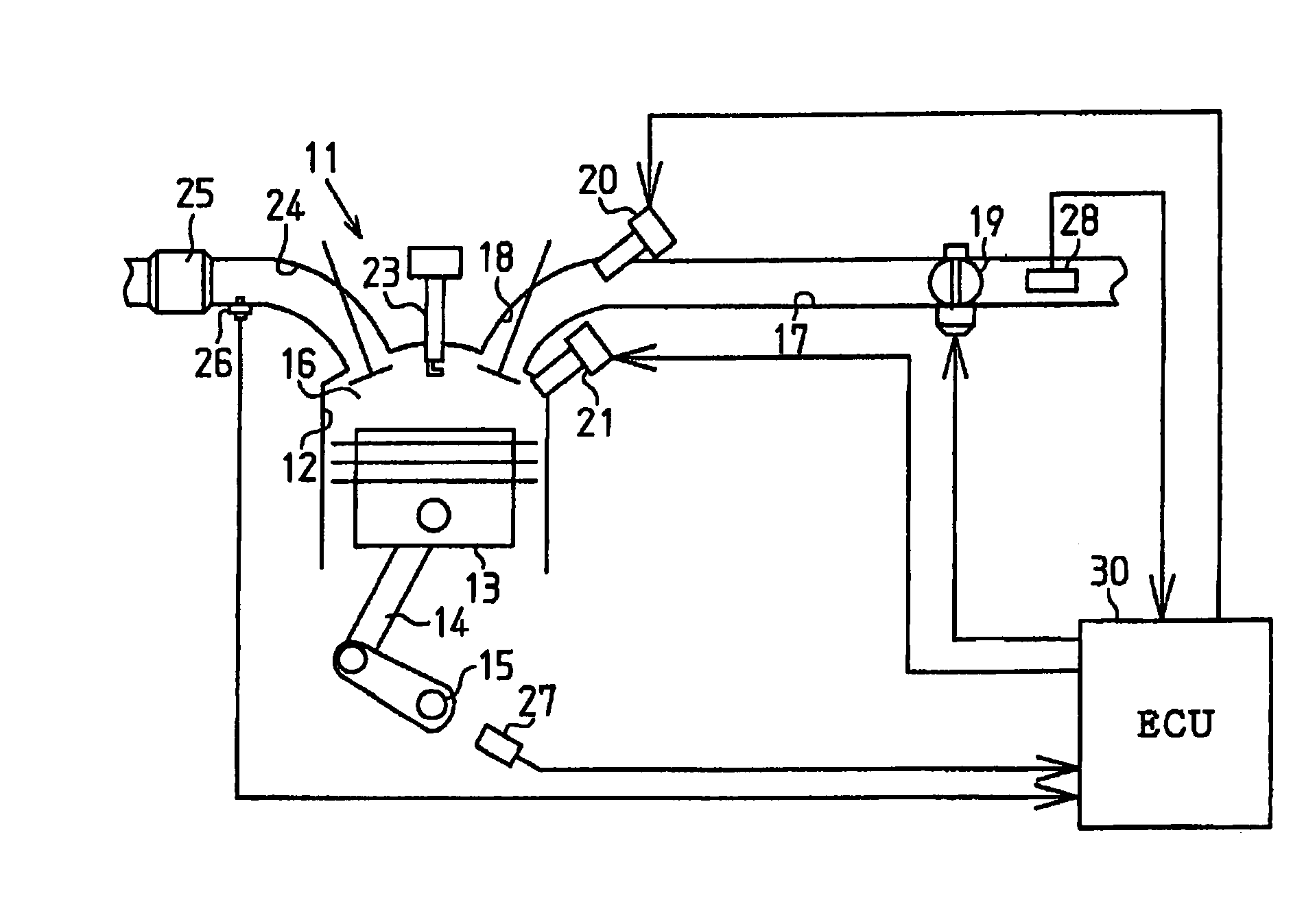
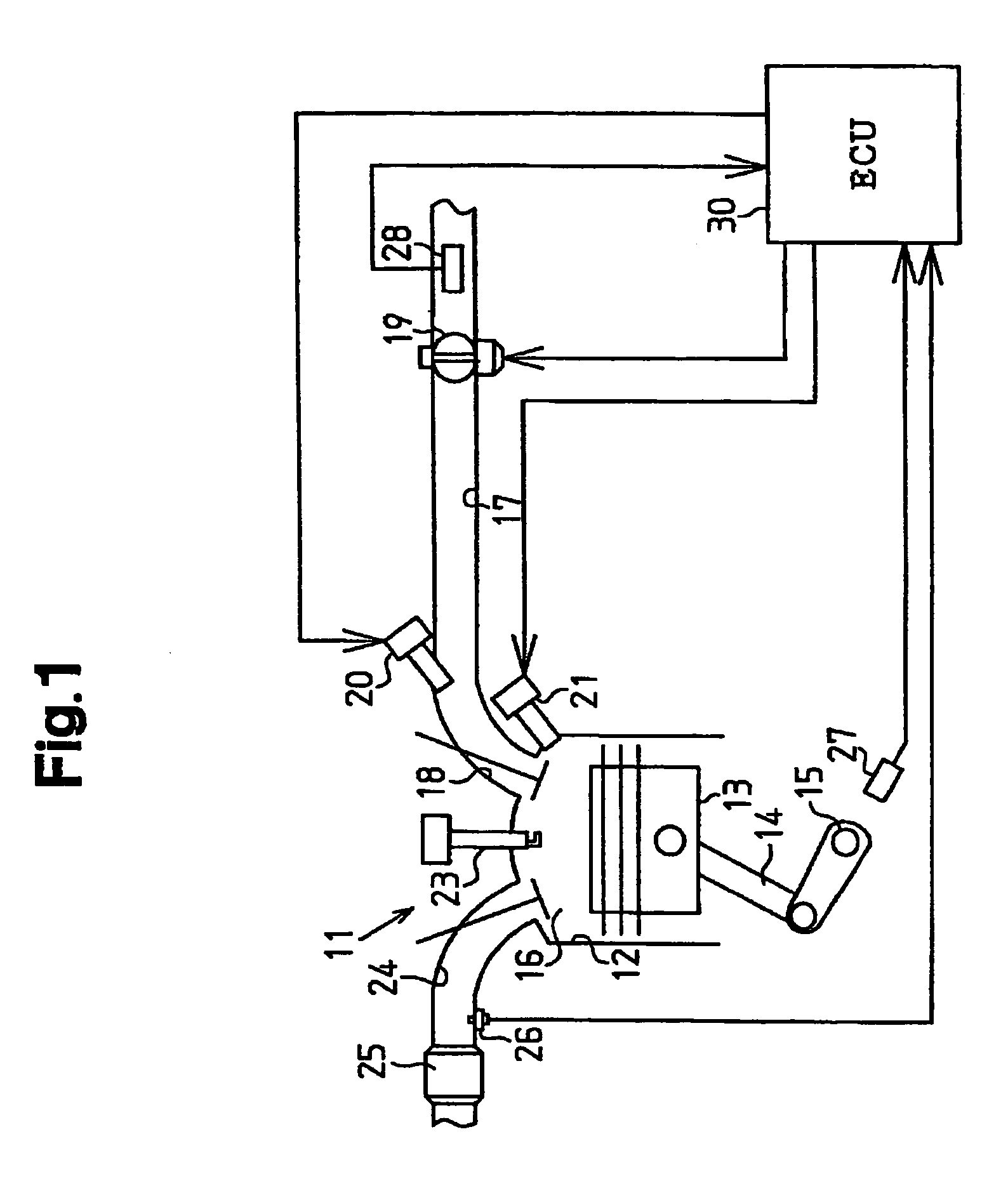
[0015]On embodiment according to the present invention will now be described with reference to the drawings. In this embodiment, the present invention is applied to a gasoline engine 11 for an automobile. As shown in FIG. 1, the engine 11, which is an internal combustion engine, includes cylinders 12. A piston 13 is accommodated in each cylinder 12 to reciprocate in the cylinder 12. Each piston 13 is coupled to a crankshaft 15, which is an output shaft of the engine 11, with a connecting rod 14. Reciprocation of each piston 13 is converted into rotation of the crankshaft 15 by the corresponding connecting rod 14.

[0016]A combustion chamber 16 is defined in each cylinder 12. Air is supplied to the combustion chamber 16 of each cylinder 12 through an intake passage 17 and an intake port 18. A throttle valve 19 is located in the intake passage 17. The throttle valve 19 is opened and closed for adjusting the amount of air (intake air amount) to be supplied to the combustion chambers 16. ...


PUM


Abstract

An electronic control unit computes a first correction value for compensating for the deviation of the actual air-fuel ratio in relation to a target air-fuel ratio when fuel is supplied to each combustion chamber from corresponding port injector and in-cylinder injector such that the ratio of the fuel injection amount of the port injector to the total fuel injection amount of the corresponding port injector and in-cylinder injector seeks a first distribution ratio. The electronic control unit also computes a second correction value for compensating for the deviation of the actual air-fuel ratio in relation to the target air-fuel ratio when fuel is supplied to each combustion chamber from the corresponding injectors such that the ratio of the fuel injection amount of the port injector to the total fuel injection amount of the corresponding injectors seeks a second distribution ratio that is different from the first distribution ratio. Further, the electromagnetic control valve corrects the fuel injection amount of each of the injectors based on the first and second distribution ratios and the first and second correction values.

Description

BACKGROUND OF THE INVENTION[0001]The present invention relates to an apparatus and method for controlling fuel injection in an internal combustion engine that includes a plurality of sets of fuel injection valves, each set corresponding to a single cylinder and supplying fuel to a combustion chamber of the corresponding single cylinder.[0002]Conventionally, as an apparatus for controlling fuel injection in an internal combustion engine, the one disclosed in Japanese Laid-Open Patent Publication No. 3-185242 is known. The fuel injection controlling apparatus of the publication includes in-cylinder injectors, each of which directly injects fuel into one of combustion chambers, and port injectors, each of which injects fuel to one of intake ports. According to the operating state of an internal combustion engine, the apparatus switches between an injection mode, in which fuel is supplied to each combustion chamber by using only the in-cylinder injector in the corresponding in-cylinder ...

Claims


Application Information

Patent Timeline
Patent Type & Authority Patents(United States)
IPC IPC(8): F02B7/00F02B23/10F02D45/00F02D41/00F02D41/02F02D41/14F02D41/34F02D41/36
CPCF02D41/008F02D41/3094F02D41/1487F02D41/1456
Inventor OOMORI, YUZURU
Owner TOYOTA JIDOSHA KK
Why Eureka
Try Eureka