Acoustical telemetry

a technology of telemetry and telemetry instruments, applied in the field of telemetry, can solve the problems of motor stalling, motor stalling, motor damage,

Inactive Publication Date: 2006-03-21
WEATHERFORD TECH HLDG LLC
View PDF14 Cites 65 Cited by
  • Summary
  • Abstract
  • Description
  • Claims
  • Application Information

AI Technical Summary

Problems solved by technology

From time to time, conditions may arise which mitigate the effectiveness of the motor of a drill string in performing its above listed functions and may even damage the motor.
For example, the motor may stall during operation.
A motor may stall for a number of reasons including setting down too much weight-on-bit, running into a tight area and pinching the bit-box, a stator failure, etc.
It is both expensive and time-consuming to pull the motor out of the wellbore each time there is doubt as to whether the motor is turning.
Another undesirable condition which may arise downhole is a leak between the interior and the exterior of the drill pipe to create a “short circuit” which reduces the effectiveness of the drilling fluid in performing its functions.
If such a leak goes undetected and is allowed to persist over time, the flow of the drilling fluid, which is typically loaded with solids, will erode or wash away enough of the material of the drill pipe at the location of the leak as to weaken the pipe to the point of separation (twist off).
Fishing operations are time consuming and expensive and not always successful.
Even if successful, the fishing operation presents a significant financial loss.
Another detrimental event that may occur is a flow restriction or blockage, which also interferes with the effectiveness of the drilling fluid.
Furthermore, a total blockage has been known to cause a rapid increase in hydraulic pressure in the drill string with eventual rupture of the drill string or the standpipe which feeds the drilling fluid to the drill string at the earth's surface.
Again, such a condition inhibits successful drilling and results in increased operating expenses.
However, such approaches are not always accurate.
Furthermore, there is a significant time delay in the pressure indication when drilling with a compressible medium, such as in the case of underbalanced drilling using nitrogen.
However, this technique is limited because some motors do not create a strong acoustical signature all the time.
Often, it is not possible to acoustically differentiate a stalled motor from a rotating motor.

Method used


Image

  • Acoustical telemetry
  • Acoustical telemetry
  • Acoustical telemetry

Examples


Embodiment Construction

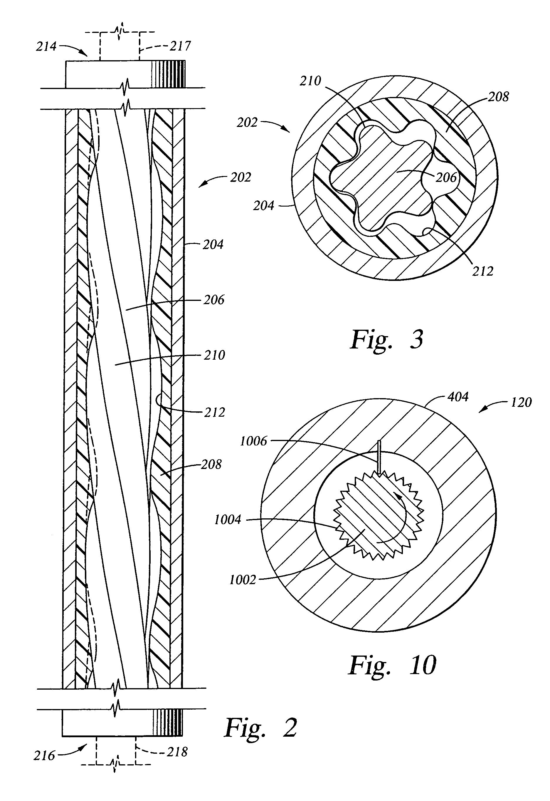
[0031]The present invention generally relates to a method and apparatus for monitoring and characterizing the operation of a transducer downhole. A transducer refers to any apparatus which converts one form of energy to another, e.g., motive fluid energy to mechanical rotational energy. Particular embodiments of a transducer are a motor and a pump. Accordingly, specific embodiments of the present invention are described with reference to a motor or a pump. However, in each case, the invention is adaptable to either. Thus, references to a “motor” or a “pump” are merely for purpose of illustration and are not limiting of the invention.

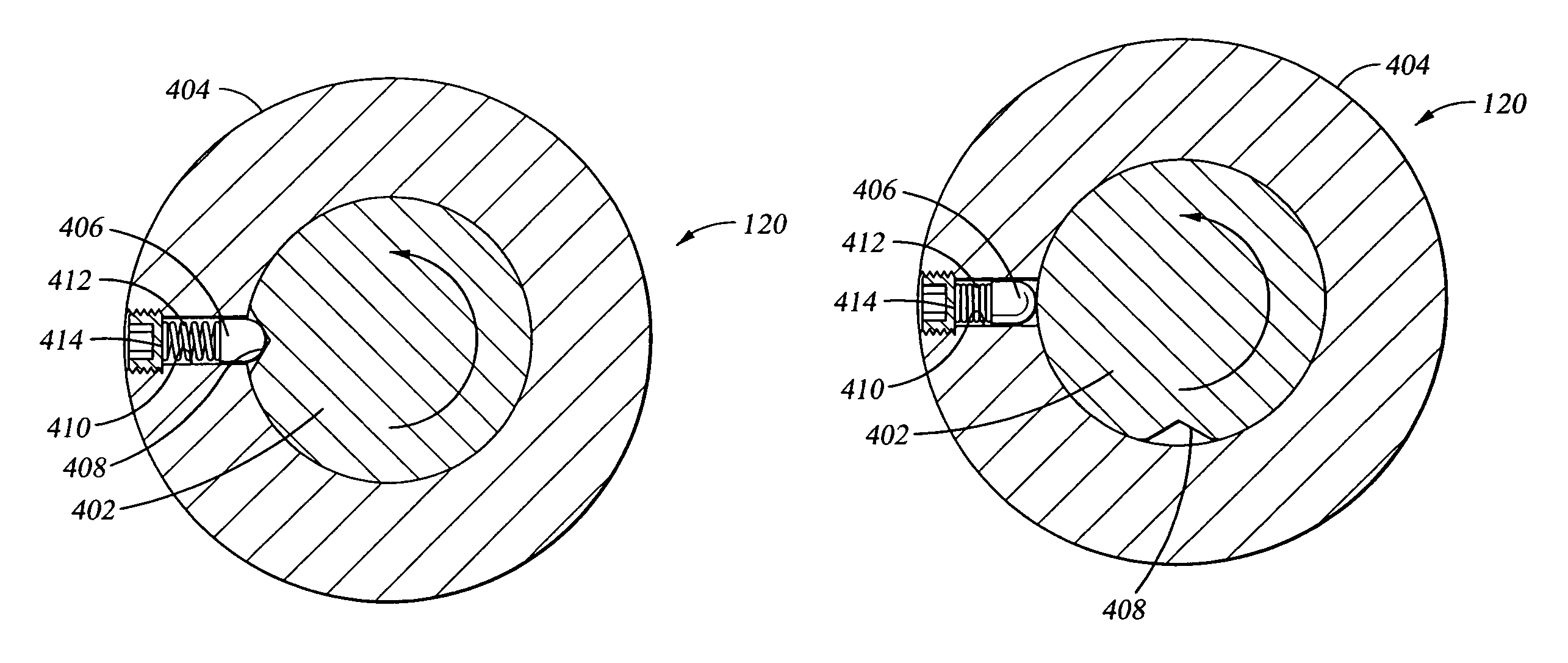
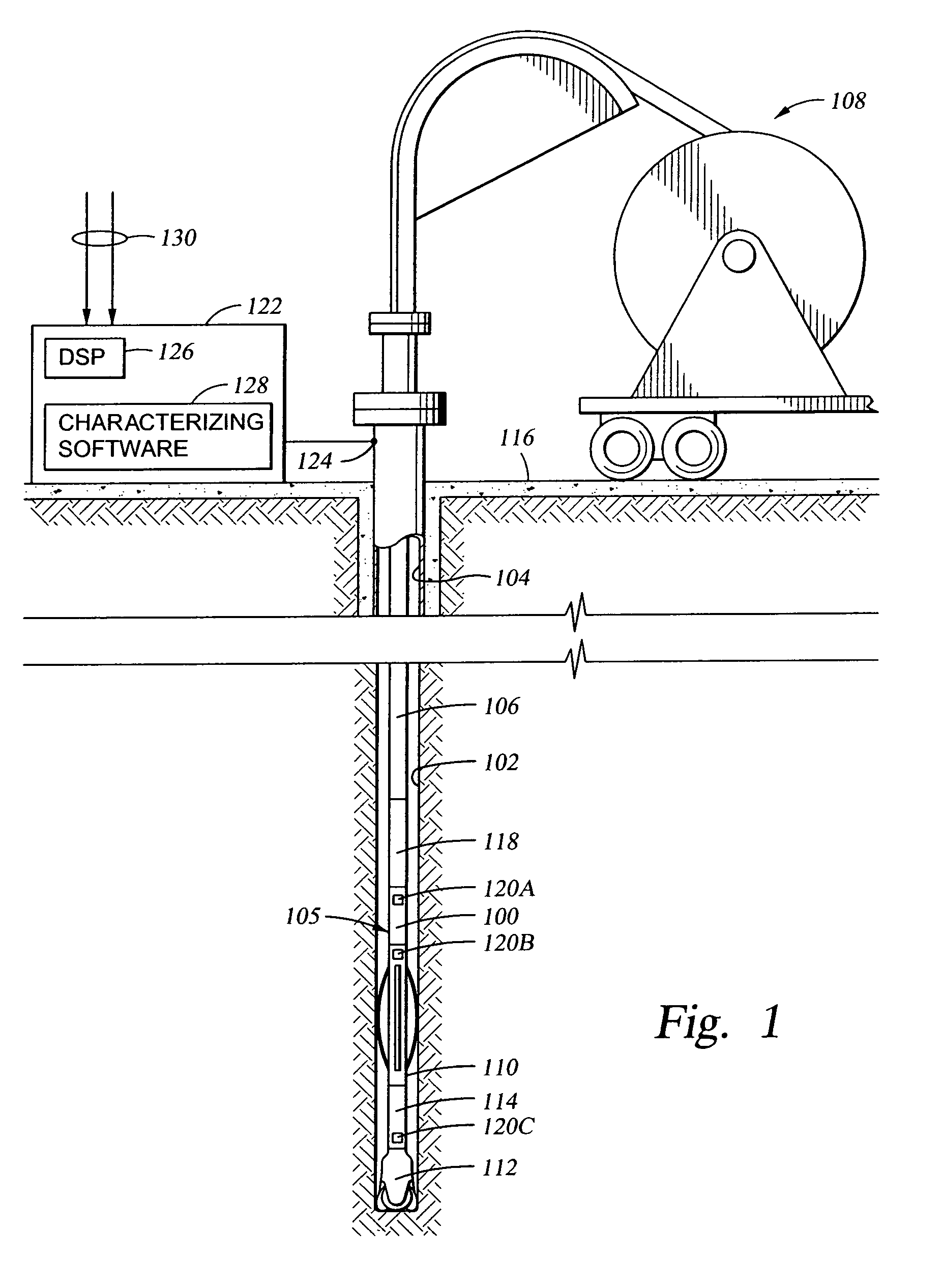
[0032]In one embodiment of the present invention, the operation of a transducer downhole is characterized by the transducer's RPMs, which may be determined by analysis of acoustic information. An acoustical source (signal generator) located on a downhole tool (e.g., a drill string) creates acoustic energy which is received and processed by a receiving un...


PUM


Abstract

Method, apparatus and article of manufacture for monitoring and characterizing the operation of a transducer (i.e., motor or pump) downhole. In particular, transducer RPMs are determined by analysis of acoustic information. An acoustical source (signal generator) located on a downhole tool (e.g., a drill string) creates acoustic energy which is received and processed by a receiving unit, which may be located at the surface of a wellbore. The acoustical source is operably connected to the transducer, so that the frequency of the signal produced by the acoustical source corresponds to the speed of the transducer. The acoustic signal of the acoustical source may then be isolated from other acoustical energy produce by downhole equipment, such as a drill bit. Having determined transducer speed by isolation of the acoustic signal, other operating parameters may be determined. Illustrative operating parameters include torque, flow, pressure, horsepower, and weight-on-bit.

Description

BACKGROUND OF THE INVENTION[0001]1. Field of the Invention[0002]Embodiments of the present invention generally relate to a method and apparatus of acoustically transmitting data to and from downhole environments.[0003]2. Description of the Related Art[0004]To recover oil and gas from subsurface formations, wellbores / boreholes are drilled by rotating a drill bit attached at an end of a drill string. The drill string includes a drill pipe or a coiled tubing (referred herein as the “tubing”) coupled to a bottomhole assembly (BHA) which, in turn, carries the drill bit at its end. The drill bit is rotated by, for example, operation of a mud motor disposed in the BHA. In this case, a drilling fluid commonly referred to as the “mud” is supplied under pressure from a surface source into the tubing during drilling of the wellbore and through the mud motor. The pressurized drilling fluid (mud) acts as a motive fluid to operate the mud motor and is then discharged at the drill bit bottom. The ...

Claims


Application Information

Patent Timeline
Patent Type & Authority Patents(United States)
IPC IPC(8): E21B47/18E21B4/02E21B47/00E21B47/16
CPCE21B4/02E21B47/16E21B47/0007E21B47/008
Inventor HAMMOND, BLAKE THOMASSHAW, JOEL D.TEALE, DAVID W.
Owner WEATHERFORD TECH HLDG LLC
Why Eureka
Try Eureka