Eureka AIR delivers breakthrough ideas for toughest innovation challenges, trusted by R&D personnel around the world.

Compacting facility for bulk goods

Inactive Publication Date: 2006-03-21
ALEXANDERWERK
View PDF9 Cites 2 Cited by
  • Summary
  • Abstract
  • Description
  • Claims
  • Application Information

AI Technical Summary

Benefits of technology

[0005]The object of the present invention is to provide a facility for compacting powdered and granulated products which produces a compacted product which is as homogeneous as possible.
[0007]Using the compacting facility according to the present invention, a homogeneous flake quality is ensured over the entire production process. For this purpose, it is essential that the crude product and further components are supplied in parallel to the screw conveyor from the various shafts from the beginning. This is possible because the components from the forward shaft(s) in the direction of conveyance only partially feed the screw conveyor, while the crude product from the last shaft fills up the screw conveyor. Due to the separated material supply occurring in the direction of conveyance of the screw conveyor, which includes the granulate recirculated by the separating device, optimum mixing of the material to be compacted results in combination with the multiple screw conveyor acting as a mixer. It is favorable for deaeration that air which is pressed out must no longer travel through the entire material column in the last shaft, which is full as a rule, but rather only the material columns, which are small in any case, in one or another of the upstream shafts, which are practically empty as a rule.

Problems solved by technology

Crude products, which are supplied as a powder or grain or a mixture thereof, are frequently not suitable for immediate further processing, e.g. into tablets in the pharmaceutical industry, because they have too high a proportion of air and / or are not sufficiently pourable.
However, a part of the air also passes through the roller gap “explosively”, due to which the roller press is stressed and runs noisily.
This is made more difficult because the mass flow of the recirculated product varies greatly.
Therefore, stabilization of the flake quality only occurs slowly in the process.

Method used


Image

  • Compacting facility for bulk goods
  • Compacting facility for bulk goods

Examples


Embodiment Construction

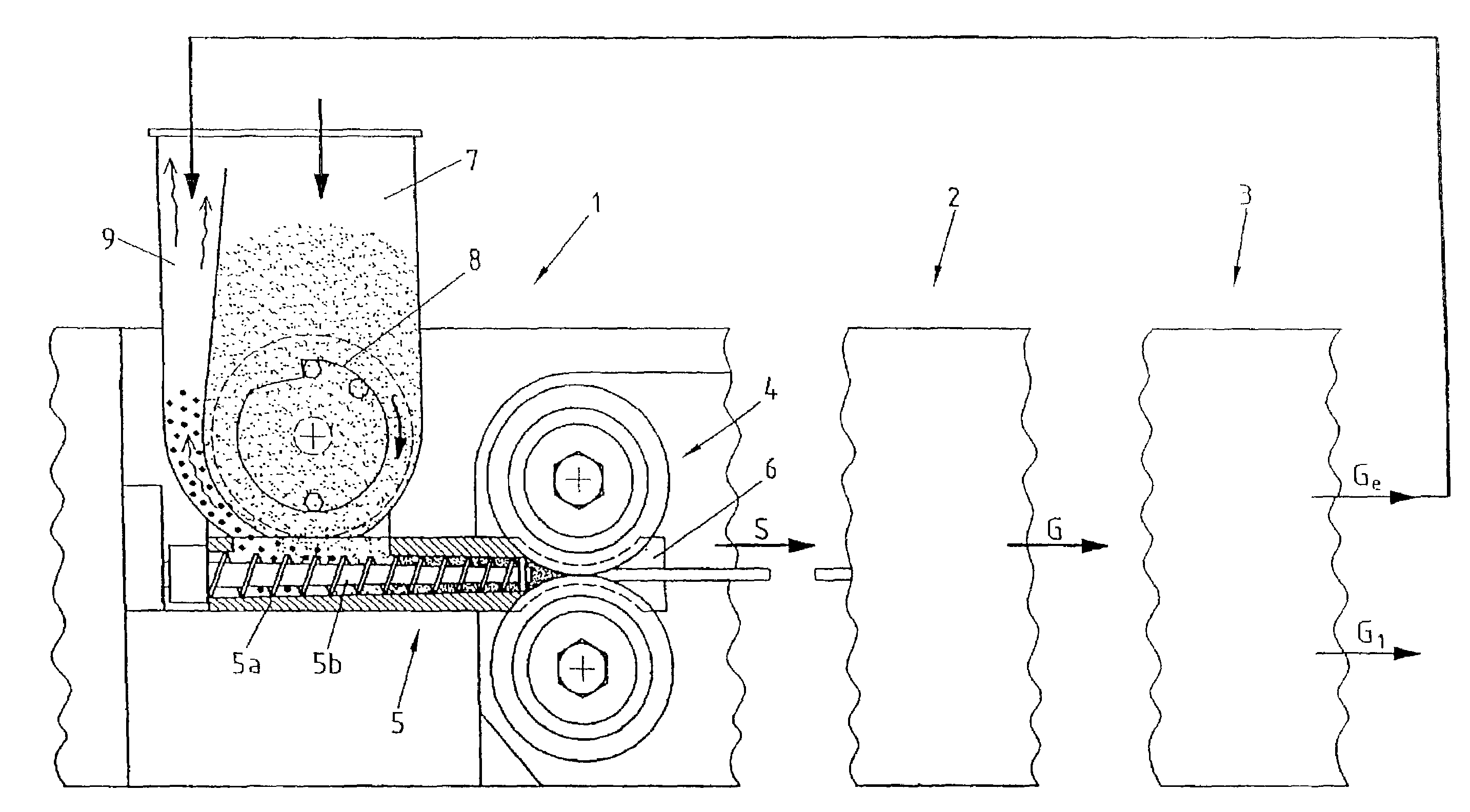
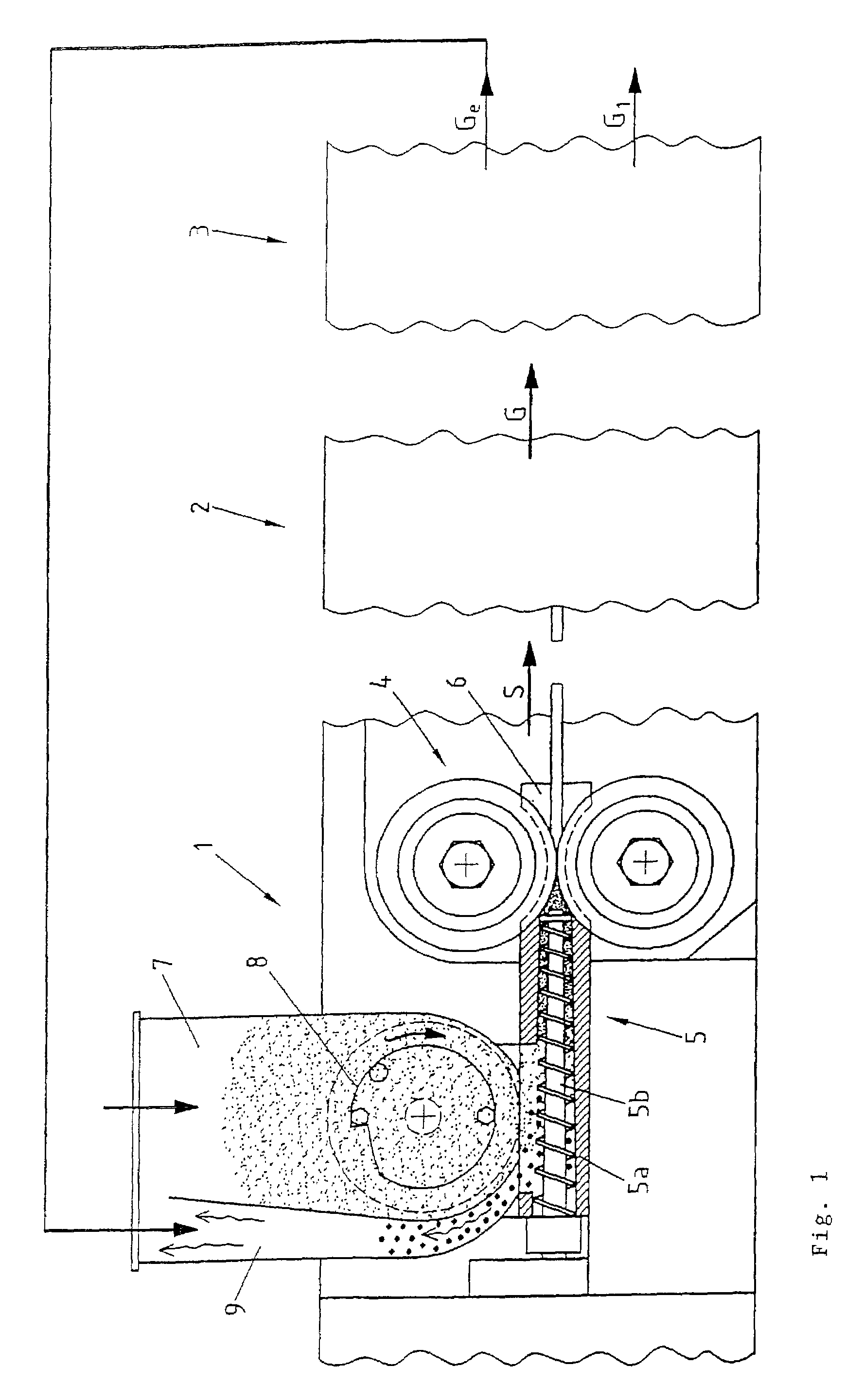
[0012]The compacting facility is made of a part 1 for compacting the crude product, a part 2 for granulating, and a part 3 for sieving the granulate.

[0013]First part 1 includes a roller press 4 having horizontal material supply. The material to be compacted is supplied to the roller gap of roller press 4 under pressure via a screw conveyor 5 having screw housing 5a and multiple screw 5b for mixing the material supplied. Screw conveyor 5 is tightly connected to the roller gap.

[0014]Roller press 4 is laterally sealed by cover plates 6. A feeding hopper for powdered to granulated product, which is divided into a forward shaft 7 and a rear shaft 9, is located over screw conveyor 5. A rotor 8 is positioned in shaft 7 for moving the crude product so that it does not remain hanging in shaft 7.

[0015]The powdered crude product is introduced into shaft 7. Screw conveyor 5 feeds it under pressure into the roller gap of roller press 4, where it is compacted into flakes S. Flakes S are subsequen...


PUM


Abstract

A compacting facility for bulk goods is disclosed. In order to generate flakes of homogeneous quality, the bulk good is conveyed to a roller press (4) via a screw conveyor (5). The roller press (4) is supplied with bulk goods of differing quality from two shafts (7,9) positioned one behind the other, the screw conveyor (5) being underfed from the first shaft (9) in the direction of conveyance with granulate, which is not suitable for further processing, arising after the roller press (4) and the rest of the feeding being from the last shaft (7) in the direction of conveyance.

Description

BACKGROUND OF THE INVENTION[0001]The present invention relates to a compacting facility for bulk goods having a roller press and a screw conveyor positioned before it, over which a feeding hopper is positioned as bulk good feeder.[0002]Crude products, which are supplied as a powder or grain or a mixture thereof, are frequently not suitable for immediate further processing, e.g. into tablets in the pharmaceutical industry, because they have too high a proportion of air and / or are not sufficiently pourable. Compacting the crude products before the further processing and subsequently granulating them is known from the patent literature (German Patent 34 31 865 C2), but above all from practice. For compacting, for example, a roller press having a screw conveyor positioned before it is used. Using the screw conveyor, the crude product is fed into the roller gap from the feeding hopper under a certain pressure. Since the roller press is sealed on both sides and the screw conveyor is conne...

Claims


Application Information

Patent Timeline
IPC IPC(8): B29C45/18B29C47/10B01J2/22B30B11/18B30B11/24B30B15/30
CPCB01J2/22B30B15/302B30B11/24B30B11/18B30B15/308
Inventor EGGERT, AXEL
Owner ALEXANDERWERK
Why Eureka
Eureka Blog
Learn More