
Top pull type front derailleur

Inactive Publication Date: 2006-03-21
SHIMANO INC
View PDF22 Cites 48 Cited by
  • Summary
  • Abstract
  • Description
  • Claims
  • Application Information

AI Technical Summary

Benefits of technology

[0009]Another object is to provide a front derailleur that is relatively easy to produce at a relatively inexpensive price.
[0010]Yet another object is to provide a front derailleur that is very easy to operate.

Problems solved by technology

Depending upon the location of the braze-on connection, the angle at which the shift cable is connected to the derailleur may change such that a large pulling force is required to shift the derailleur.
In other words, if the angle of the cable relative to the derailleur becomes too small, the derailleur may become difficult to shift.
Therefore, a front derailleur may not operate very well on frames with very small seat tubes.

Method used


Image

  • Top pull type front derailleur
  • Top pull type front derailleur
  • Top pull type front derailleur

Examples


second embodiment

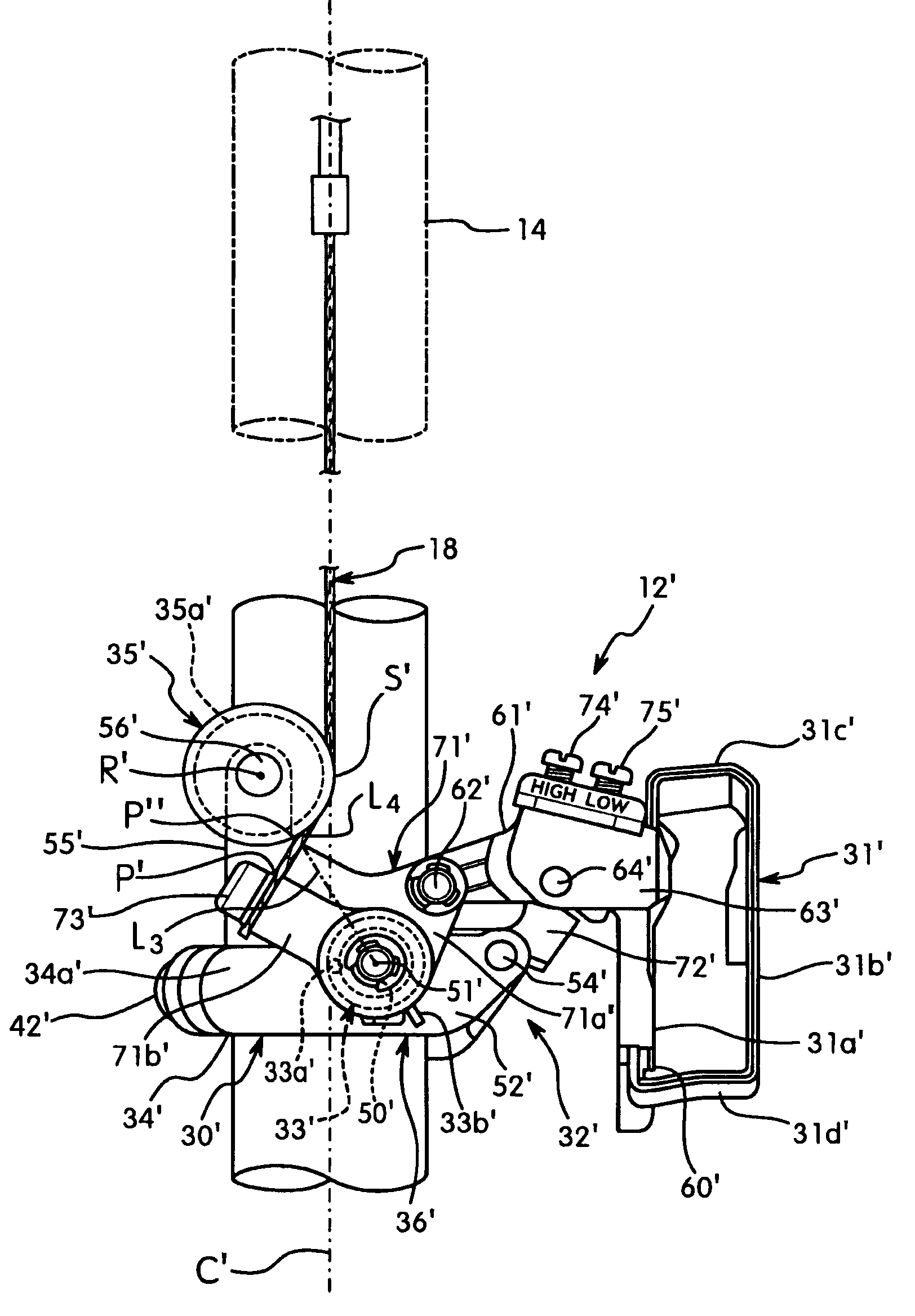
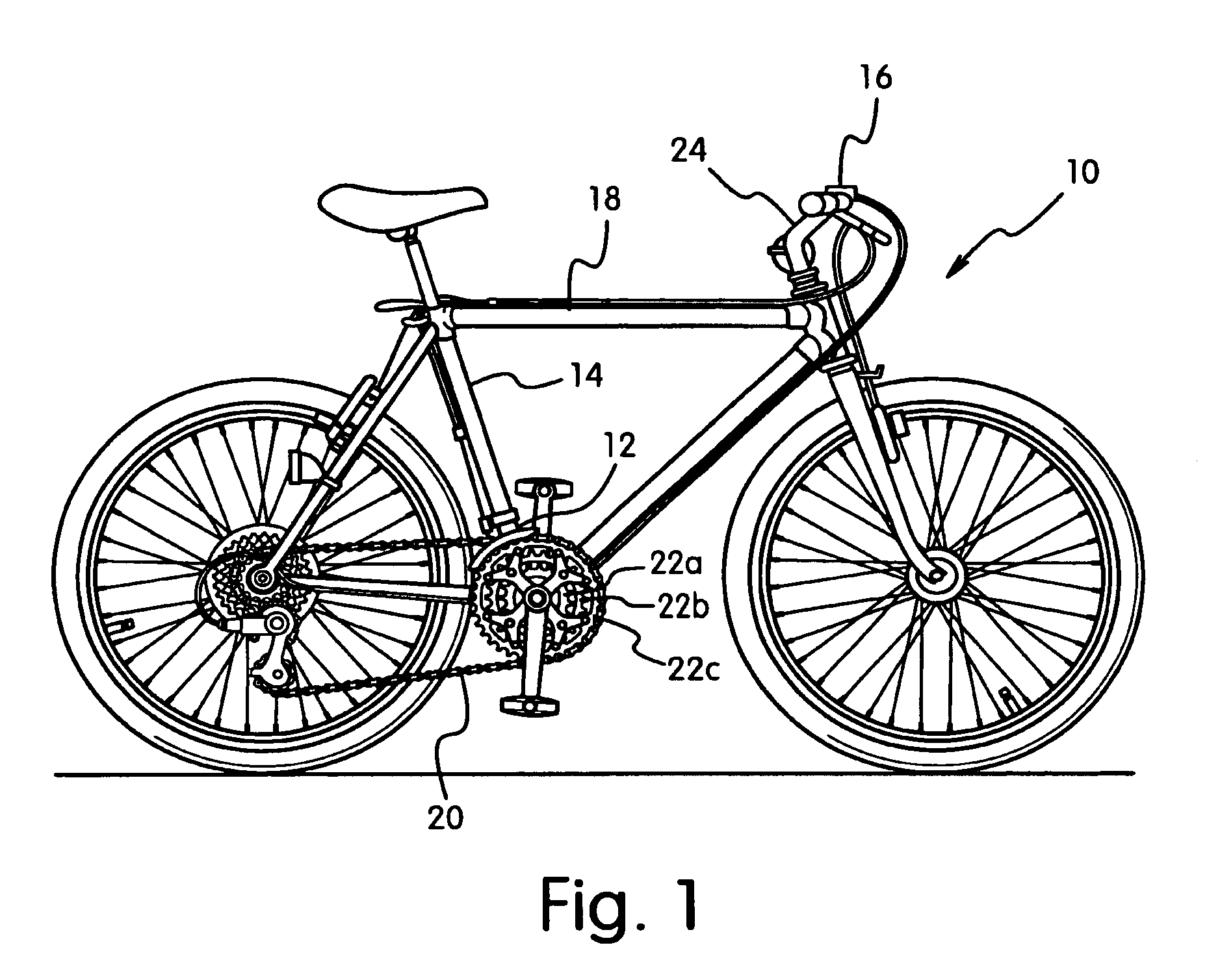
[0044]Referring now to FIGS. 8-12, a front derailleur 12′ in accordance with a second embodiment will now be explained. The front derailleur 12′ is installed on the bicycle 10 such that the front derailleur 12′ is operated by the front shifter 16 via the cable 18. Basically, the front derailleur 12′ includes a bicycle frame clamping band or tubular clamping member 30′, a chain guide 31′, a linkage assembly 32′ and a biasing member 33′. The linkage assembly 32′ is coupled between the clamping band 30′ and the chain guide 31′ to move the chain guide 31′ laterally towards and away from the clamping band. The linkage assembly 32′ is preferably designed such that the biasing member (torsion spring) 33′ normally biases the chain guide 31′ in a transverse direction towards the frame of the bicycle 10.

[0045]The clamping band 30′ is located below the chain guide 31′ such that the chain guide 31′ moves from a retracted (low gear) position to an extended (high gear) position when the cable 18 ...


PUM


Abstract

A top pull type front derailleur is designed to move or shift a chain between two or more sprockets for changing gears. The front derailleur basically has a bicycle frame clamping band, a linkage assembly and a chain guide. The linkage assembly includes a cable connection point and is arranged between the bicycle frame clamping band and the chain guide to move the chain guide laterally towards and away from the clamping band. The clamping band has a top pull cable guide surface that is configured and arranged relative to the clamping band to guide a cable from vertically above the clamping band to the cable connection point when the front bicycle derailleur is operatively mounted to a bicycle frame. Preferably, the top pull cable guide surface is formed on a peripheral surface of a roller that is rotatably mounted on the clamping band.

Description

BACKGROUND OF THE INVENTION[0001]1. Field of the Invention[0002]The present invention generally relates to a front derailleur for a bicycle. More specifically, the present invention relates to a front derailleur for a bicycle.[0003]2. Background Information[0004]Bicycling is becoming an increasingly more popular form of recreation as well as a means of transportation. Moreover, bicycling has become a very popular competitive sport for both amateurs and professionals. Whether the bicycle is used for recreation, transportation or competition, the bicycle industry is constantly improving the various components of the bicycle. The various components of the bicycle are usually mounted to the bicycle frame. Some components of the bicycle that have been extensively redesigned are the bicycle derailleurs.[0005]One component that is mounted to the bicycle frame is the front derailleur. Generally speaking, the front derailleur is typically secured to the seat tube of the bicycle frame. The fr...

Claims


Application Information

Patent Timeline
IPC IPC(8): F16H61/04B62M9/1342B62M9/135B62M9/137
CPCB62M9/1342B62M9/137B62M9/135
Inventor NANKO, YOSHIAKIKIRIMOTO, KANJI
Owner SHIMANO INC
Learn More