Vacuum separation, transport and collection system for immiscible liquids

a vacuum system and immiscible liquid technology, applied in the direction of water cleaning, liquid displacement, separation processes, etc., can solve the problems of reducing the operational efficiency of the vacuum system, too long a resident time, and insufficient resident time of the suction particulate contaminants, so as to efficiently dispose of the collected immiscible liquid, minimize the possibility of solid particulates clogging the vacuum line, and achieve the effect of reducing the possibility of solid particulates clogging

Inactive Publication Date: 2006-03-21
KIRCHNER EDWARD C
View PDF5 Cites 8 Cited by
  • Summary
  • Abstract
  • Description
  • Claims
  • Application Information

AI Technical Summary

Benefits of technology

[0008]A controller is secured in communication with the vacuum generator means for applying a vacuum to the collector and the holder for a predetermined vacuum duty cycle for periodically removing separated immiscible liquid from the holder into the collector. In a preferred embodiment, the controller is also secured in communication with the separator for controlling operation of the separator for a predetermined separator duty cycle. The controller therefore may include one or more timers that operate the separator for a separator duty cycle, for example for thirty minutes of each five and one-half hour period, and that operate the vacuum generator for a vacuum duty cycle of two minutes of each ten minutes while the separator is operating. By having the vacuum generator and vacuum line cooperatively structured to draw a flow rate of separated immiscible liquid from the holder at a much greater rate than a flow rate of separated immiscible liquid from the separator, suspended particulate contaminants do not have adequate resident time in the separated immiscible liquid within the holder and vacuum line to settle in the holder or vacuum line or to plug the vacuum line. The controller may also be in communication with a volume sensor within the collector so that the controller shuts off the vacuum generator whenever a volume or amount of collected immiscible liquid within the collector reaches a predetermined amount to prevent overfilling of the collector. The system therefore provides for automated and efficient separation, transport and collection of the immiscible liquid. By use of the vacuum generator for transport and collection, contaminants in the immiscible liquid cannot degrade performance of the system because such contaminants do not contact the vacuum generator or controller. Application of the vacuum also assists in degassing the immiscible liquid, and removing gaseous components of the immiscible liquid without compromising storage efficiency of the collector.
[0009]In a preferred embodiment, the controller and vacuum generator are secured within a common housing, and the housing includes an integral sealing cap for sealing the collector to the housing. In such an embodiment, the collector may be simply unscrewed or otherwise detached from the housing while the controller has terminated operation of the vacuum generator to efficiently dispose of the collected immiscible liquid. If the vacuum generator is started after the collector is detached, no separated liquid could flow from and be spilled out of the holder because the removed collector interrupts the vacuum to the holder. This is a significant safety feature that is an additional advantage over pump systems. The immiscible liquid may then be poured out of the collector, after which the collector is re-attached to the housing to place the system ready for operation again. In a further embodiment, the collector may include automatic discharging apparatus for removing the separated immiscible liquid from the collector.
[0010]In another embodiment, the vacuum system includes a screen secured between the separator and the holder, wherein a shortest internal diameter of a vacuum line directing flow of the immiscible liquid between the holder and the collector is at least two times longer than a longest distance across any of the passageways defined within the screen. Such a relationship between the screen and the vacuum line minimizes any possibility of solid particulates clogging the vacuum line. In an additional embodiment, the vacuum line is dimensioned to enhance degassing by optimizing a relationship between an internal diameter of the vacuum line and a length of the vacuum line between the holder and the collector in order to exceed a minimal residence time for the liquid passing through the vacuum line. Enhanced degassing of the immiscible liquid passing through the vacuum line is achieved by providing adequate time for bubble formation of the gas within the liquid so that when the mixed phase fluid flows out of a spray nozzle into the collector the bubbles burst and degassing occurs. However, too long a resident time will reduce operational efficiency of the vacuum system. Consequently, enhanced efficiency is achieved when a minimal residence time to achieve degassing is exceeded. For example, an internal diameter of about one-quarter inch (0.25″) and a length of about eight feet (8.0′) produces nearly optimal degassing of the collected, separated liquid passing through the vacuum line to the collector.
[0012]In a further embodiment, the vacuum generator is a “venturi effect” generator, wherein a stream of compressed air passes through a venturi chamber generating a vacuum within the vacuum line that is secured to the venturi chamber. The venturi chamber is within the housing, and exhausted pressurized air is discharged from the venturi chamber and through the housing and over controller components then through cooling holes defined within the housing to provide for cooling of the controller. Additionally, the controller and skimmer may be powered by a reduced voltage, such as twelve volts direct current, to minimize risk to users of the system.
[0014]It is a more specific purpose to provide a vacuum separation, transport and collection system for immiscible liquids that provides for automated, efficient, safe, and durable separation, transport and collection of a separated immiscible liquid.

Problems solved by technology

By having the vacuum generator and vacuum line cooperatively structured to draw a flow rate of separated immiscible liquid from the holder at a much greater rate than a flow rate of separated immiscible liquid from the separator, suspended particulate contaminants do not have adequate resident time in the separated immiscible liquid within the holder and vacuum line to settle in the holder or vacuum line or to plug the vacuum line.
However, too long a resident time will reduce operational efficiency of the vacuum system.

Method used


Image

  • Vacuum separation, transport and collection system for immiscible liquids
  • Vacuum separation, transport and collection system for immiscible liquids
  • Vacuum separation, transport and collection system for immiscible liquids

Examples


Embodiment Construction

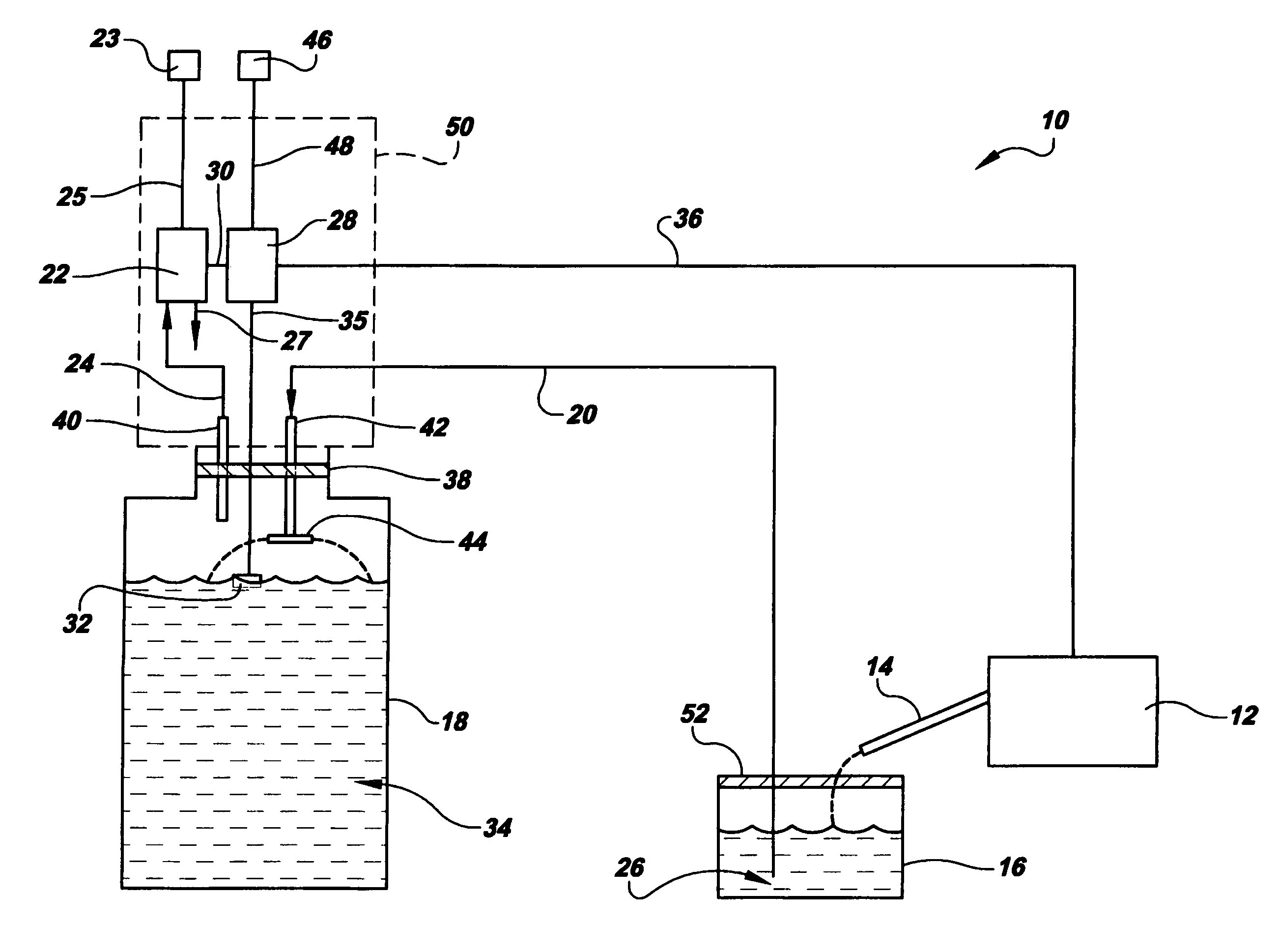
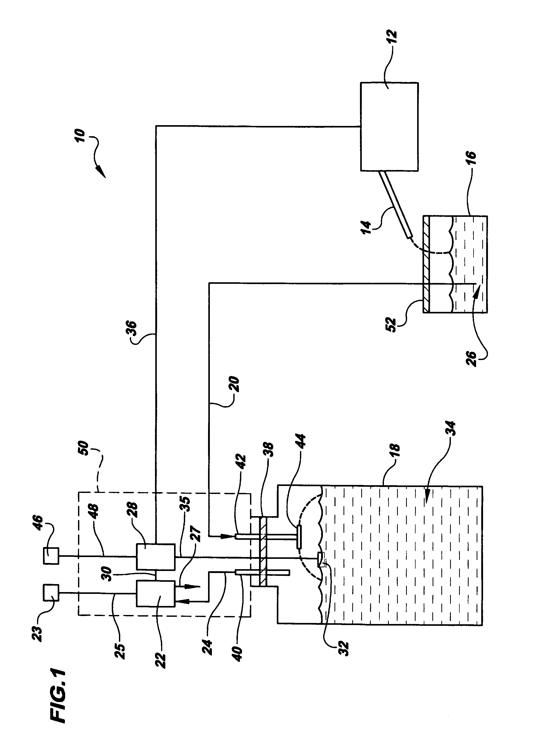
[0019]Referring to the drawings in detail, a vacuum separation, transport and collection system for immiscible liquids is shown in FIG. 1, and is generally designated by the reference numeral 10. The vacuum system 10 includes a separator means 12 for separating two or more immiscible liquids. The separator means may be any known separator capable of separating immiscible liquids, such as a skimmer separator shown in the aforesaid U.S. Pat. No. 4,274,957 to Koller. An exemplary skimmer is available under the trademark RUSTLICK® Tramp Oil Skimmer, part number 78,012 from the ITW ROCOL NORTH AMERICA company, of Glenview, Ill. Additionally, a skimmer separator such as in the Koller Patent is available under the trademark OYBELT®, from the OYBELT®Corporation, of North Lake, Wis. The separator means 12 directs a separated immiscible liquid through a spout 14 into a holder 16, that is secured in fluid communication with the separator means 12. The vacuum system 10 also includes a collector...


PUM

PropertyMeasurementUnit
lengthaaaaaaaaaa
voltageaaaaaaaaaa
vacuumaaaaaaaaaa

Abstract

A vacuum separation, transport and collection system for immiscible liquids includes a separator (12) for separating two immiscible liquids such as oil and a water-based coolant, and for directing the separated immiscible liquid into a holder (16). A collector (18) is secured through a vacuum line (20) with the holder (16) and a vacuum generator (22) applies a vacuum to the collector (18) and holder (16). A controller (28) controls the vacuum generator (22) to apply a vacuum to the collector (18) and the holder (16) for a predetermined vacuum duty cycle for periodically removing separated immiscible liquid (26) from the holder (16) into the collector (18). Contaminants in the immiscible liquid cannot degrade performance of the system because such contaminants do not contact the vacuum generator (22) or controller (28).

Description

CROSS REFERENCE TO RELATED APPLICATION[0001]This Application claims the benefit of U.S. Provisional Application Ser. No. 60 / 455,894 filed on Mar. 19, 2003, and entitled “Skimmer, transport mechanism, collection and separation system”.TECHNICAL FIELD[0002]The present invention relates to systems for separating and collecting immiscible liquids, and especially relates to an improved, efficient, vacuum powered system for separating, transporting and collecting immiscible liquids such as oil and water-based solutions.BACKGROUND ART[0003]It is well known that water-based coolants are commonly used to cool machine tools during cutting or other operations of the tools. Typically, the coolant solutions are applied to heated components of the tool, and either recirculated through machine or collected for subsequent usage. Such used water-based coolants frequently contain contaminants such as lubricating oils from the machine tools, and metal particles. These coolants may be recirculated and ...

Claims


Application Information

Patent Timeline
Patent Type & Authority Patents(United States)
IPC IPC(8): C02F1/40
CPCB01D17/0214B01D17/044C02F1/40C02F2101/32C02F2103/16
Inventor KIRCHNER, EDWARD C.
Owner KIRCHNER EDWARD C
Why Eureka
Try Eureka