Power supply rail controller

a technology of power supply rail and controller, which is applied in the direction of diagnostic recording/measuring, applications, instruments, etc., can solve the problems of high preamp power consumption, achieve the effects of avoiding signal distortion, reducing power dissipation, and increasing in magnitud

Active Publication Date: 2006-03-21
JPMORGAN CHASE BANK NA
View PDF3 Cites 877 Cited by
  • Summary
  • Abstract
  • Description
  • Claims
  • Application Information

AI Technical Summary

Benefits of technology

[0010]Yet another aspect of a power supply rail controller operates on an analog component having a signal input, a power input and a signal output. A voltage controller provides a control output responsive to the signal output.

Problems solved by technology

A larger supply voltage, however, resu

Method used


Image

  • Power supply rail controller
  • Power supply rail controller
  • Power supply rail controller

Examples


Embodiment Construction

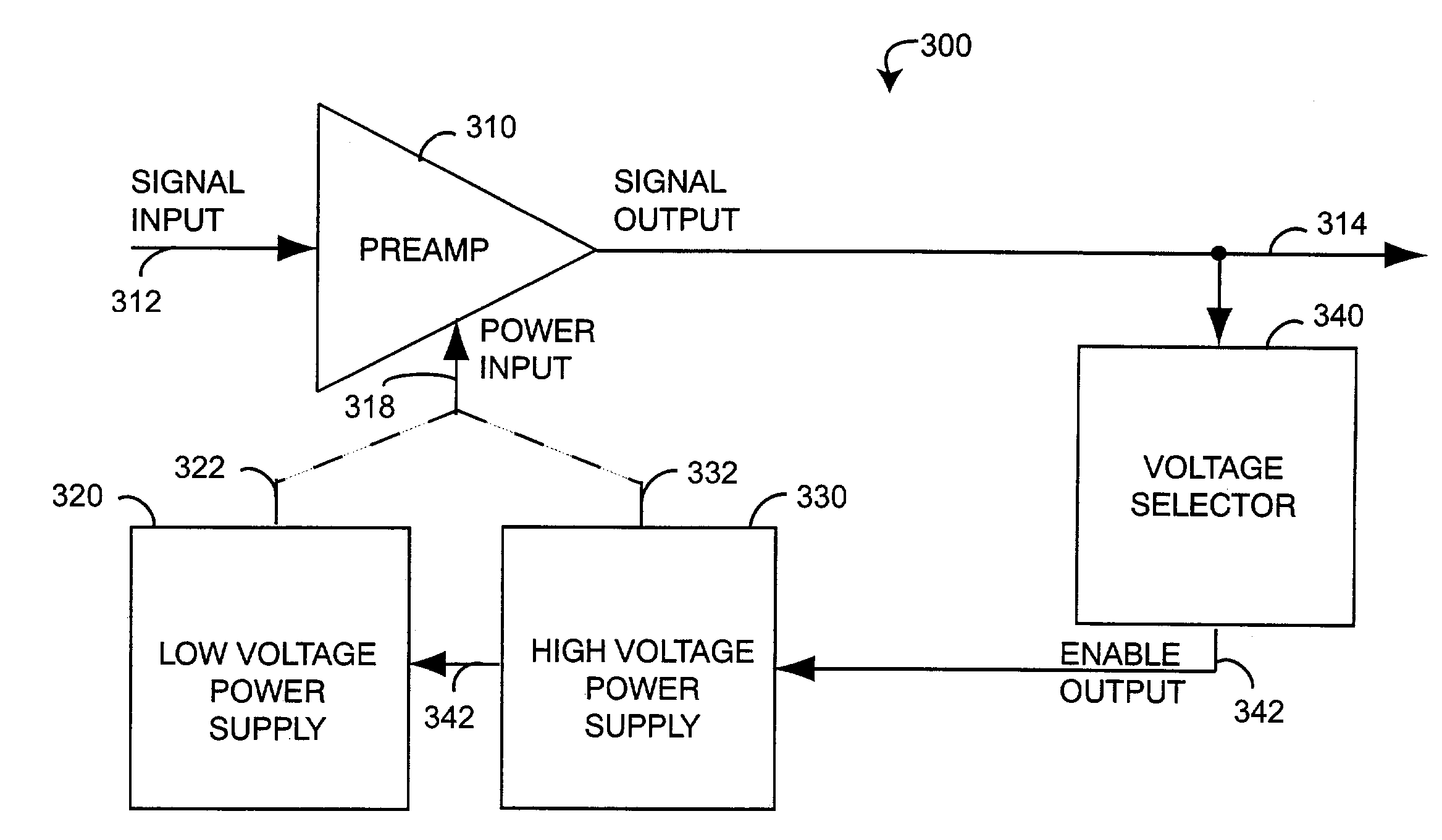
[0017]FIG. 3 generally illustrates a power supply rail controller 300 having an preamplifier (preamp) 310, a low voltage power supply 320, a high voltage power supply 330 and a voltage selector 340. The preamp 310 has a signal input 312, a signal output 314 and a power input 318. The controller 300 advantageously lowers the preamp 310 power consumption by operating from the low voltage power supply 320 when possible and the high voltage power supply 330 when necessary to avoid saturation of the signal output 314 as the signal amplitude approaches the power supply rail. This situation can potentially occur during high ambient light conditions, as described above. The voltage selector 340 monitors the signal output 314 and generates an enable output 342 accordingly. Specifically, the enable output 342 nominally selects the low voltage power supply 320 for low preamp power dissipation and switches to the high voltage power supply 330, raising the preamp power supply rail to prevent sig...


PUM


Abstract

A power supply rail controller operates on an analog component having a signal input, a power input and a signal output. A voltage controller provides a control output responsive to the signal output. A power supply generates a voltage for the power input, where the voltage is responsive to the control output. The voltage is reduced in magnitude to reduce power dissipation and increased in magnitude to avoid signal distortion.

Description

CROSS-REFERENCE TO RELATED APPLICATIONS[0001]The present application claims priority benefit under 35 U.S.C. §119(e) from U.S. Provisional Application No. 60 / 351,751, filed Jan. 25, 2002, entitled “Differential Input, Power Efficient Pulse Oximeter Preamplifer,” which are incorporated herein by reference.BACKGROUND OF THE INVENTION[0002]A detector preamplifier is an optical receiver component utilized in a variety of applications including pulse oximetry. Pulse oximetry is a noninvasive, easy to use, inexpensive procedure for monitoring blood oxygen that has gained rapid acceptance in a wide variety of medical applications, including surgical wards, intensive care units, general wards and home care. A pulse oximeter sensor detects the light absorption characteristics of blood perfused tissue, and a corresponding monitor performs a blood spectral analysis based upon the sensor signal. By monitoring for decreases in the arterial oxygen supply, pulse oximeters reduce the risk of accide...

Claims


Application Information

Patent Timeline
IPC IPC(8): H01J40/14A61B5/00
CPCA61B5/14551A61B2560/0214A61B2560/0209
Inventor DALKE, DAVIDSMITH, ROBERTAL-ALI, AMMARDIAB, MOHAMED K.COVERSTON, RONALD
Owner JPMORGAN CHASE BANK NA
Why Eureka
Try Eureka