Single photon emission computed tomography system

a computed tomography and single photon technology, applied in tomography, instruments, diaphragm/collimeter handling, etc., can solve the problems of imposing significant costs on hospitals providing spect services, limiting their penetration into the community, and limited their availability in physicians' offices

Inactive Publication Date: 2006-03-21
HIGHBROOK HLDG
View PDF23 Cites 24 Cited by
  • Summary
  • Abstract
  • Description
  • Claims
  • Application Information

AI Technical Summary

Problems solved by technology

Despite these compelling factors, the size and cost constraints of current systems have greatly limited their penetration into the community and have particularly limited their availability in physicians' offices.
In addition, the large space requirements of current systems have imposed significant costs on hospitals providing SPECT services.
Current SPECT systems have additional limitations.
These cables are repeatedly flexed during system operation and are a frequent cause of equipment breakdown.
This is painful for most patients and impossible for some.
In addition, the supine position is uncomfortable for many patients, particularly for those with back problems.
Many patients feel claustrophobic when inside the equipment.
The narrow platform required to permit camera rotation around the patient is uncomfortable for large individuals and is often perceived as insecure or precarious by those undergoing
Despite its many advantages, SPECT imaging is not yet avai...

Method used


Image

  • Single photon emission computed tomography system
  • Single photon emission computed tomography system
  • Single photon emission computed tomography system

Examples


Embodiment Construction

[0057]Throughout this description, the preferred embodiment and examples shown should be considered as exemplars rather than as limitations on the present invention.

I. General Overview

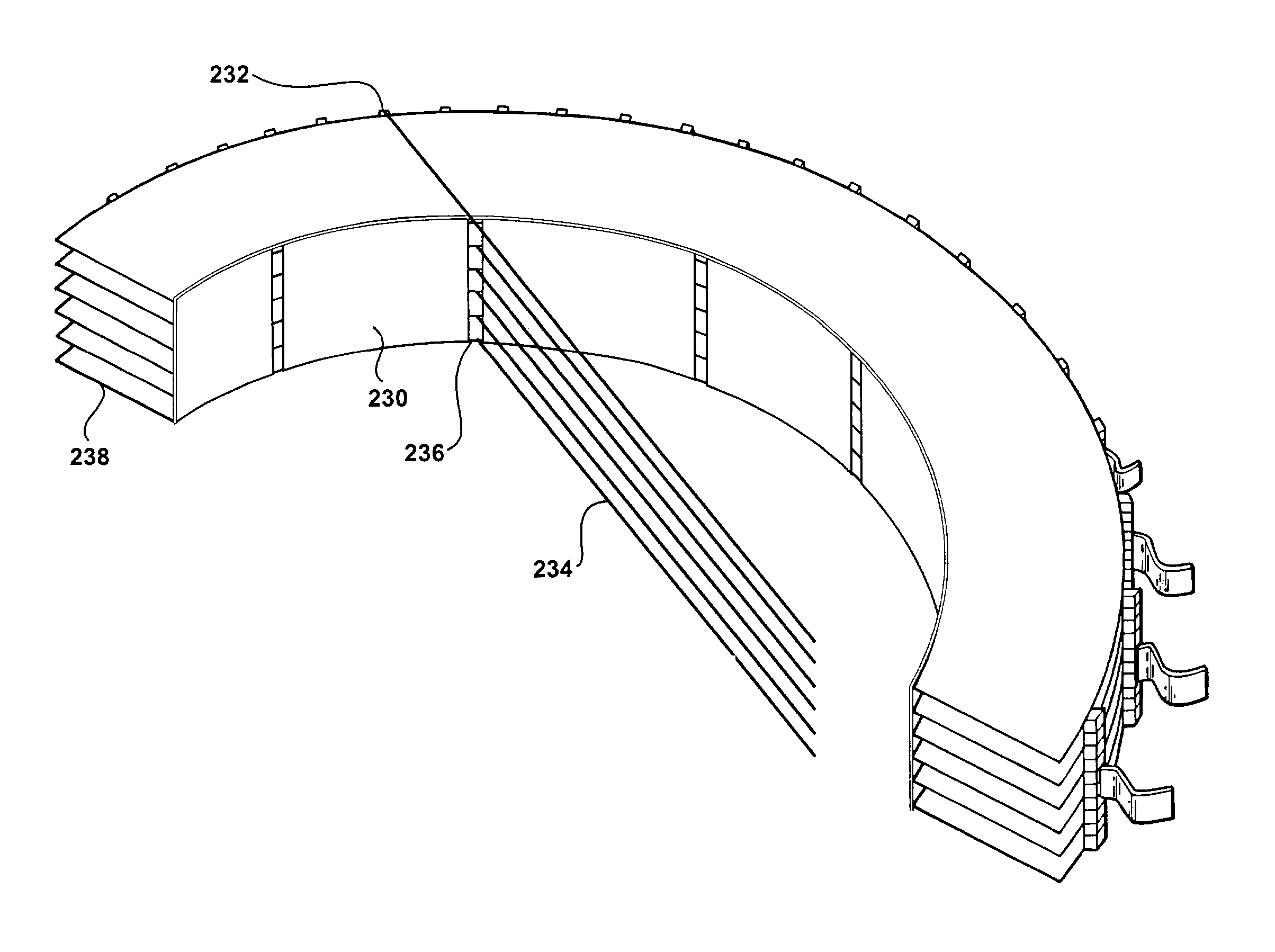
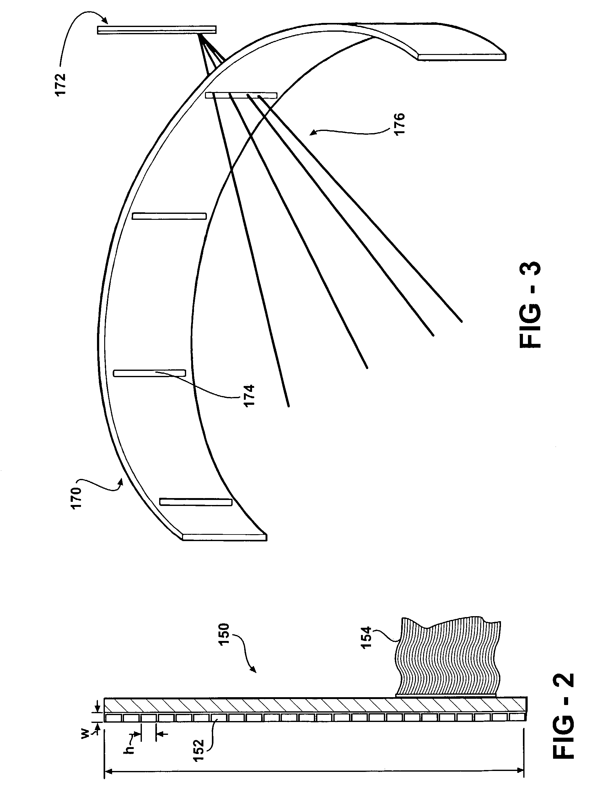
[0058]The present invention comprises a system for performing single photon emission computed tomography (SPECT). The system includes a radiation detector assembly consisting of a multiplicity of radiation detector modules preferably positioned around an arc, typically over 180°–360°. In-plane (axial) collimation is provided by a movable arc or ring extending over an angular range similar to that of the radiation detector assembly (typically 180°–360°). Cross-plane (longitudinal) collimation is provided by a plurality of vanes or sheets of photon-attenuating material held in a stationary position and oriented parallel to the transaxial plane (perpendicular to the longitudinal axis). Optionally, these vanes may be separated by sheets of a radiolucent spacer material such as Styrofoam® or other plastic. ...


PUM


Abstract

A single photon emission computed tomography system produces multiple tomographic images of the type representing a three-dimensional distribution of a photon-emitting radioisotope. The system has a base including a patient support for supporting a patient such that a portion of the patient is located in a field of view. A longitudinal axis is defined through the field of view. A detector module is adjacent the field of view and includes a photon-responsive detector. The detector is operable to detect if a photon strikes the detector. A photon-blocking member is positioned between the field of view and the detector. The blocking member has an aperture slot for passage of photons aligned with the aperture slot. A line of response is defined from the detector through the aperture. A collimating assembly includes a plurality of generally parallel collimating vanes formed of a photon attenuating material. The vanes are spaced apart so as to find a plurality of gaps, with the gaps each having a height. Each of the vanes has a front edge directed toward the field of view and a back edge directed towards the detector. The front-to-back depth of each of the vanes is greater than 10 times the height of the gaps. The plurality of vanes is disposed between the detector and the field of view such that only photons passing through one of the gaps can travel from the field of view to the detector. A displacement device moves either the detector module or the photon-blocking member relative to the other so that the aperture is displaced relative to the detector and the line of response is swept across at least a portion of the field of view.

Description

CROSS-REFERENCE TO RELATED APPLICATIONS[0001]This application is a continuation-in-part of U.S. patent application Ser. No. 09 / 549,435, filed Apr. 14, 2000 now U.S. Pat. No. 6,525,320, which claims the benefit of U.S. Provisional Applications having Ser. No. 60 / 129,239 filed Apr. 14, 1999, and Ser. No. 60 / 151,378 filed Aug. 30, 1999, all of which are incorporated herein in their entirety by reference.BACKGROUND OF THE INVENTION[0002]Medical radionuclide imaging (Nuclear Medicine) is a key component of modern medical practice. This methodology involves the administration, typically by injection, of tracer amounts of a radioactive substance, which subsequently localizes in the body in a manner dependent on the physiologic function of the organ system being studied. The radiotracer emissions, most commonly gamma photons, are imaged with a detector outside the body, creating a map of the radiotracer distribution within the body. When interpreted by an appropriately trained physician, th...

Claims


Application Information

Patent Timeline
IPC IPC(8): G01T1/166G01TG01T1/164G01T1/20
CPCA61B6/037G01T1/1642
Inventor JUNI, JACK E.
Owner HIGHBROOK HLDG
Why Eureka
Try Eureka