

Axial tube assembly for a motor
a technology of axial tube and motor, which is applied in the direction of supporting/enclosed/casing, dynamo-electric machines, and magnetic circuit shapes/forms/construction, etc., can solve the problems of noise generation and uneven rotation, and achieve the effect of reliable positioning of the bearing of the motor
- Summary
- Abstract
- Description
- Claims
- Application Information
AI Technical Summary
Benefits of technology
Problems solved by technology
Method used
Image

Examples
Embodiment Construction
[0031]Preferred embodiments of the present invention are now to be described hereinafter in detail, in which the same reference numerals are used in the preferred embodiments for the same parts as those in the prior art to avoid redundant description.
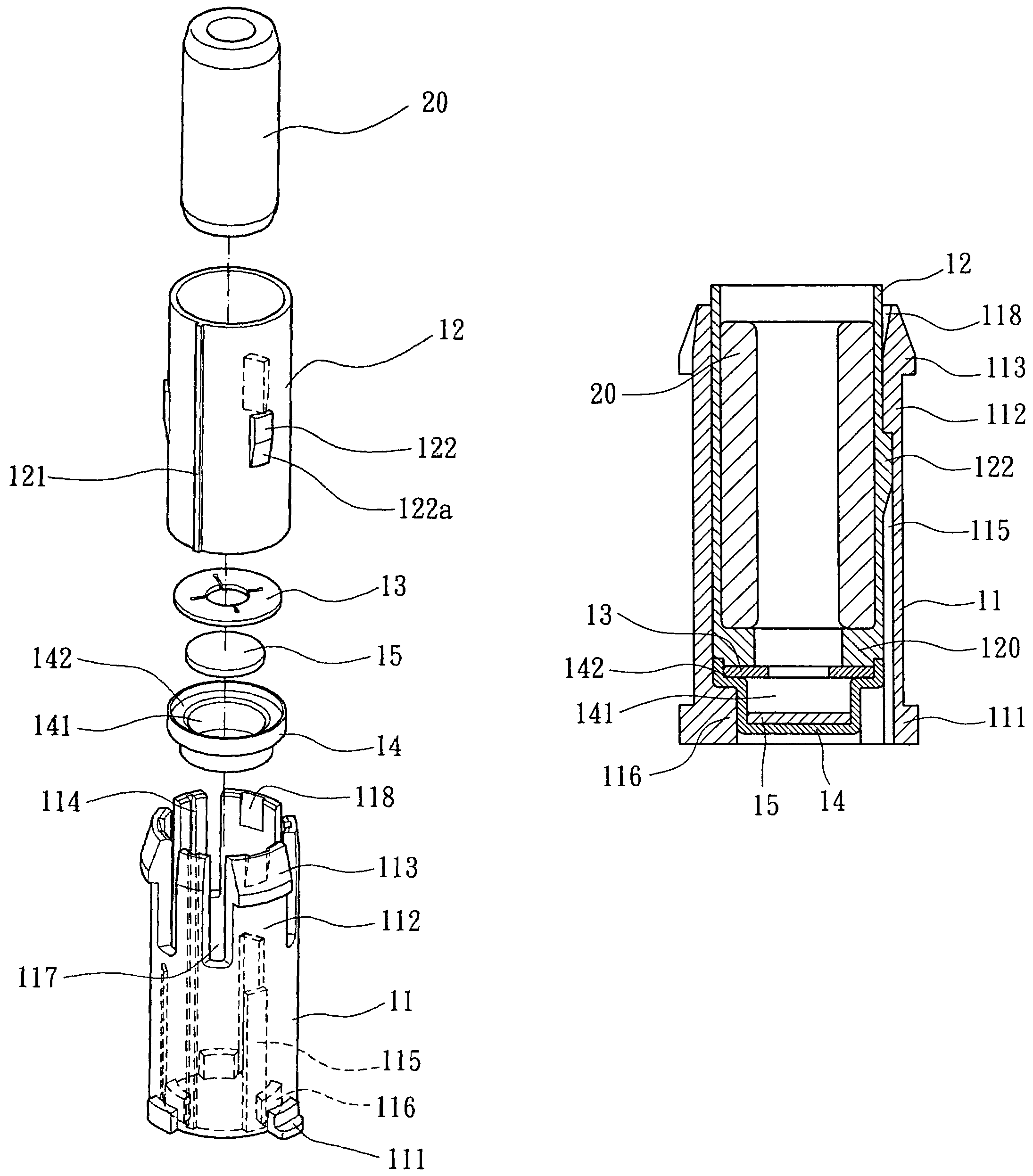
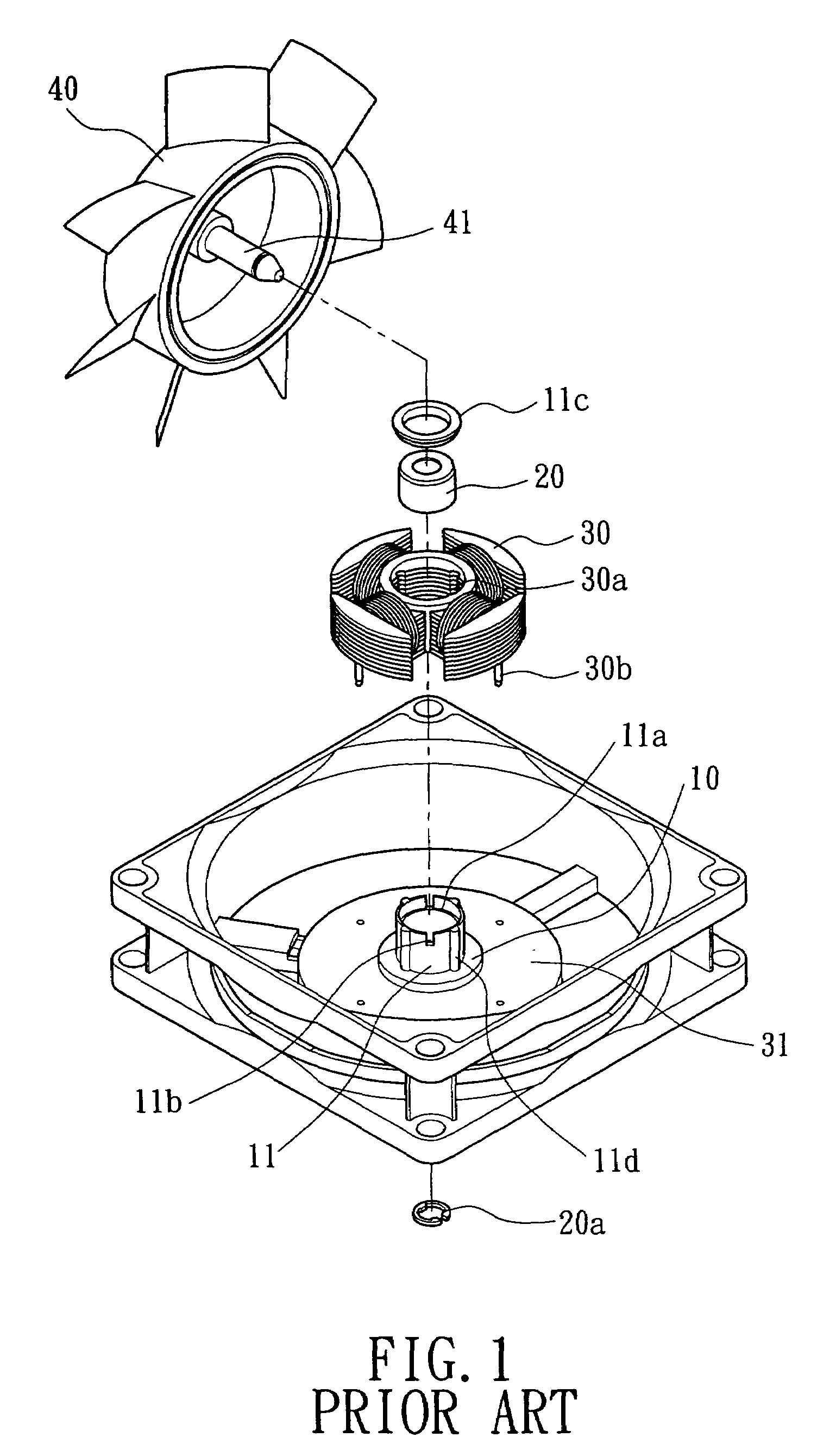
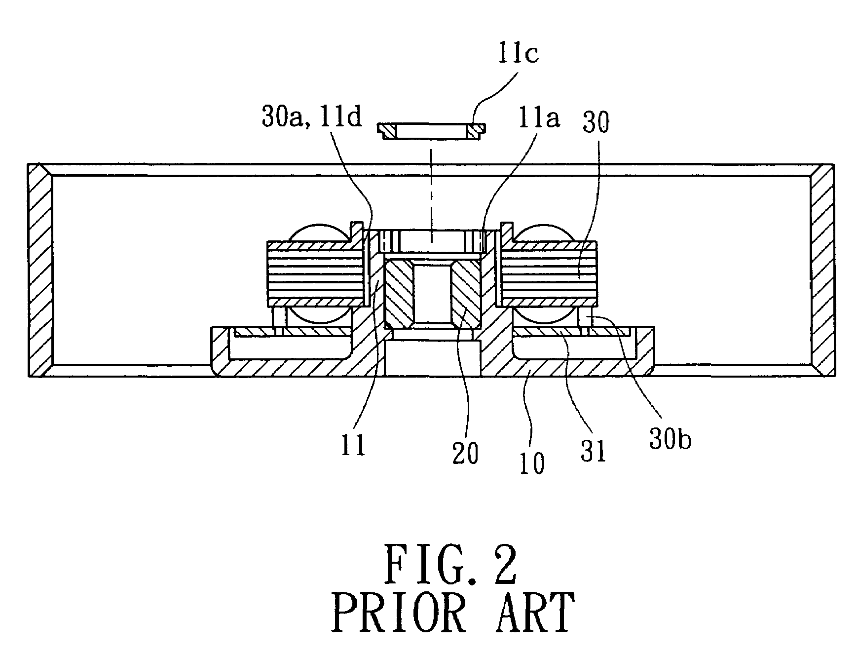
[0032]Referring to FIGS. 3 through 5, a first embodiment of an axial tube assembly for a motor in accordance with the present invention includes an axial tube 11 and a sleeve 12. The axial tube 11 can be mounted to a casing 10 and engaged with a bearing 20, a stator 30, a circuit board 31, and a rotor 40, thereby forming a motor such as a miniature brushless D.C. motor, as shown in FIG. 6.
[0033]The axial tube 11 is preferably made of a plastic material and includes plurality of engaging blocks 111 on a lower end of an outer periphery thereof. A plurality of protrusions 116 are formed on a lower end of an inner periphery of the axial tube 11. Preferably, the protrusions 116 are spaced by regular intervals and symmetrically disposed. Furt...
PUM
 Abstract
Description
Claims
Application Information