
Projection type cathode ray tube device

a cathode ray tube and projection type technology, applied in the field of cathode ray tube devices, can solve the problems of generating the shape distortion of the electron beam, called deflection distortion, and achieve the effects of enhancing the color slurring correction efficiency, enhancing the focusing function of display images, and correcting deflection distortion

Inactive Publication Date: 2006-03-21
HITACHI DISPLAYS
View PDF8 Cites 2 Cited by
  • Summary
  • Abstract
  • Description
  • Claims
  • Application Information

AI Technical Summary

Benefits of technology

[0006]Recently, to enhance the color slurring correction efficiency while reducing a deflection power supplied to a deflection circuit and enhancing focusing characteristics of a displayed image, there has been developed a projection type cathode ray tube adopting a different-diameter neck system having the constitution in which the outer diameter of a neck portion at a position where a deflection yoke is mounted is made smaller than the outer diameter of the neck portion at a position where an electron gun is housed. BY mounting the above-mentioned convergence yoke for performing the color slurring correction to the neck portion of this projection type cathode ray tube adopting a different-diameter neck system where the outer diameter dimension is relatively small (small neck-diameter portion), it is possible to narrow the inner diameter of the convergence yoke per se and hence, it is possible to enhance the color slurring correction sensitivity on the screen of the projection type image display device.
[0007]Further, in improving the above-mentioned focusing characteristics, the effect of the improvement can be enhanced by increasing the diameter of a main lens of the electron gun. Accordingly, by mounting the main lens to the neck portion having a relatively large outer diameter dimension (large neck-diameter portion), the lens diameter can be increased and hence, an image quality on a screen of the projection type image display device can be enhanced. Further, by mounting the deflection yoke as close as possible to the electron gun, the deflection efficiency is enhanced. That is, corresponding to the decrease of the outer diameter dimension of the neck portion, the deflection power can be reduced. To be more specific, the deflection power differs by approximately 25% between a case in which the deflection yoke is mounted on the small-diameter neck portion and a case in which the deflection yoke is mounted on the large-diameter neck portion. The projection type cathode ray tube device adopting the different-diameter neck type projection type cathode ray tube device which mounts the deflection yoke on the small neck-diameter portion and inserts the electron gun in the large neck-diameter portion can exhibit the approximately same image quality compared to the projection type cathode ray tube device which is constituted of only the large neck diameter portion and, at the same time, can suppress a deflection current.
[0010]Accordingly, it is an object of the present invention to provide a projection type cathode ray tube device adopting a different-diameter neck system which can enhance a focusing function of display images and, at the same time, can enhance the color slurring correction efficiency, and further can correct the deflection distortion whereby the image quality in a peripheral portion of a screen can be enhanced.
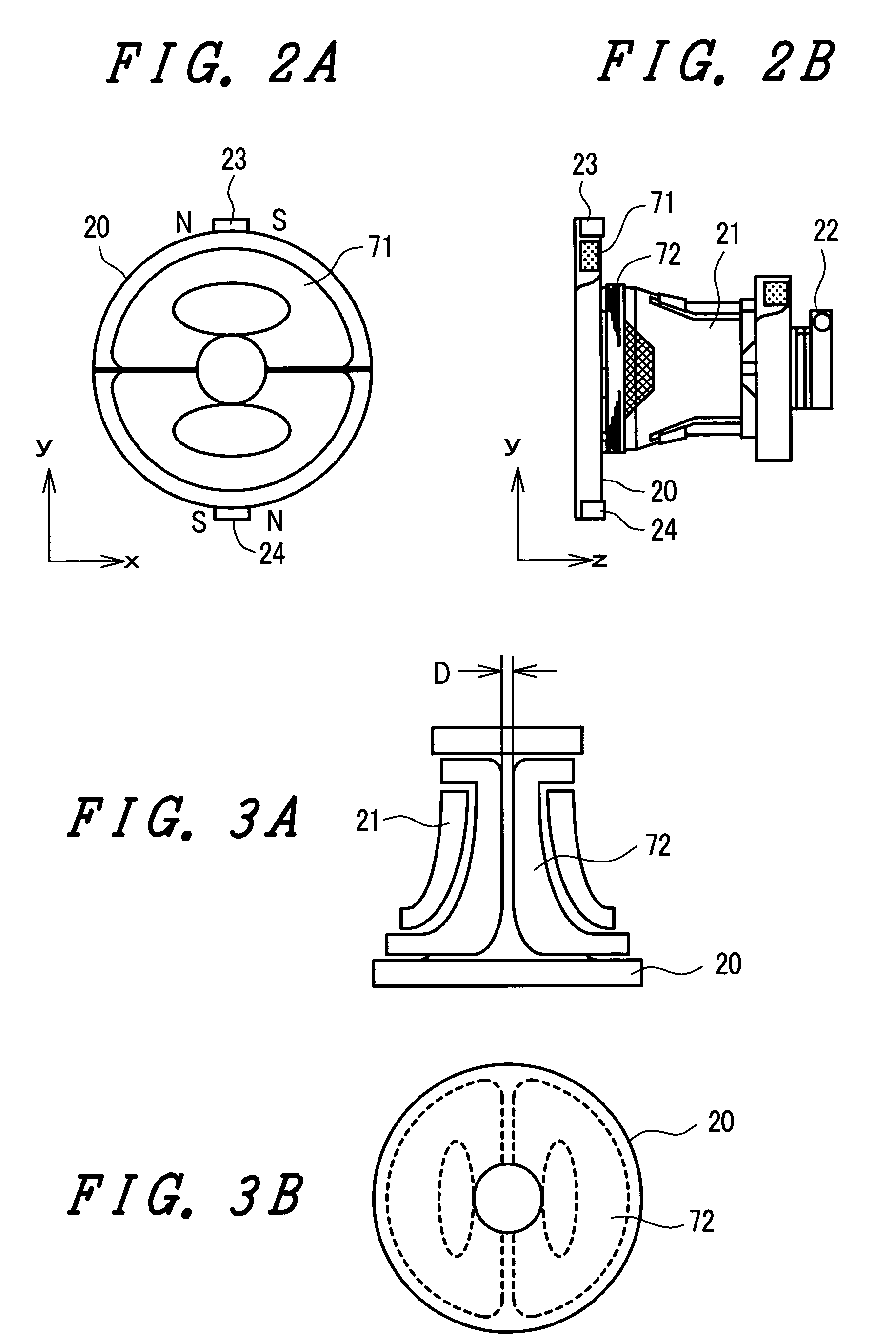
[0011]A projection type cathode ray tube device according to the present invention is constituted such that first magnets having different polarities in the horizontal direction are arranged at upper and lower sides of an opening portion of a deflection yoke, and the first magnet which is arranged at the upper side of the opening of the deflection yoke and the first magnet which is arranged at the lower side of the opening of the deflection yoke have different polarities in the lateral direction. Due to such a constitution, it is possible to correct a locus of an electron beam which enters the inside of a deflection magnetic field and can correct the electron beam distorted in the longitudinal direction to an electron beam shape which is a substantially circular shape.
[0012]Another projection type cathode ray tube device according to the present invention is constituted such that first magnets having different polarities in the horizontal direction are arranged at upper and lower sides of an opening portion of a deflection yoke, the first magnet which is arranged at the upper side of the opening of the deflection yoke and the first magnet which is arranged at the lower side of the opening of the deflection yoke have different polarities in the lateral direction, and second magnets having different polarities in the tube axis direction of a cathode ray tube are formed in the periphery of the opening portion of the deflection yoke. Due to such a constitution, it is possible to correct an electron beam which is distorted in the longitudinal direction to an approximately circular shape and to correct an electron beam which is distorted in the radial direction to an approximately circular shape.

Problems solved by technology

However, in the projection type cathode ray tube adopting the different-diameter neck system, electron beams irradiated from the electron guns arranged in the large neck-diameter portion strongly receive an influence of a deflection magnetic field of the deflection yoke, thus generating the distortion of the shape of the electron beams, that is, the so-called deflection distortion relatively in the peripheral portion of a screen.

Method used


Image

  • Projection type cathode ray tube device
  • Projection type cathode ray tube device
  • Projection type cathode ray tube device

Examples


Embodiment Construction

[0024]Preferred embodiments of the present invention are explained hereinafter in conjunction with drawings which show the embodiments.

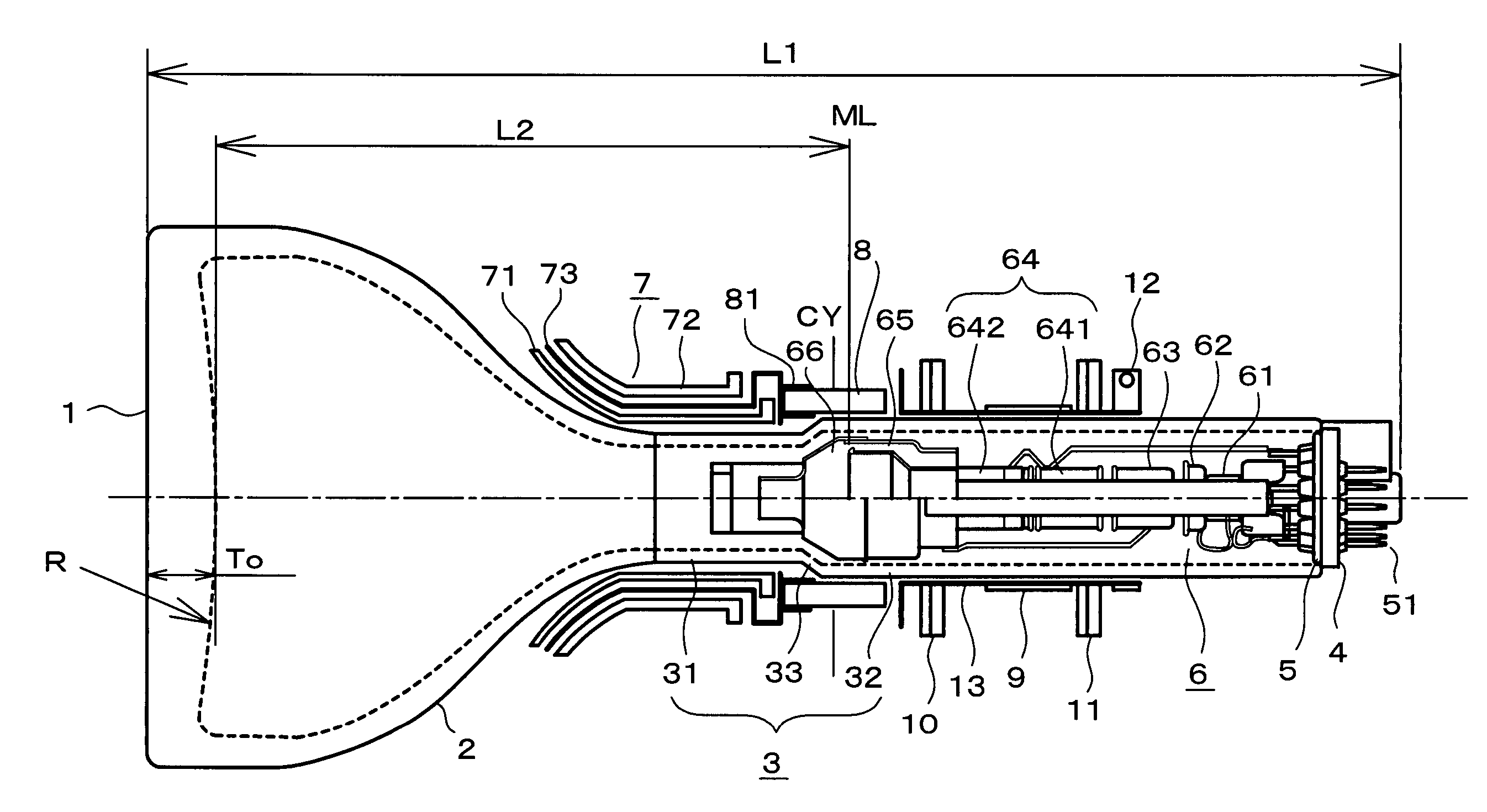
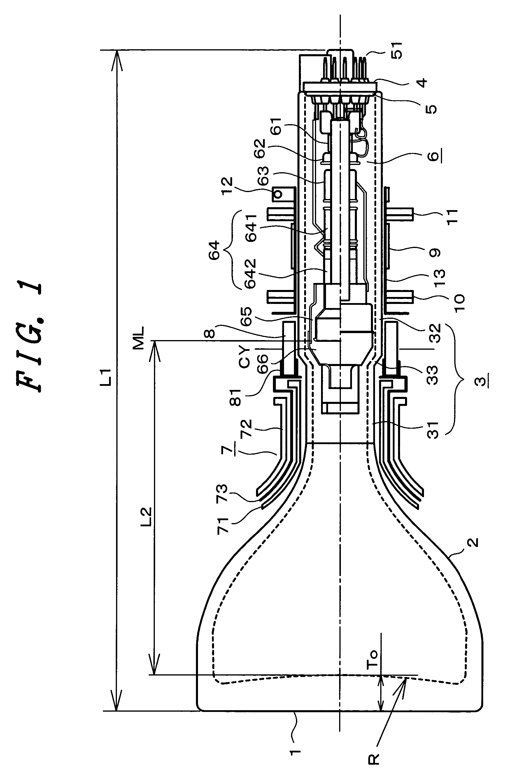
[0025]FIG. 1 is a partial cross-sectional view for explaining an embodiment of a projection type cathode ray tube device according to the present invention. In FIG. 1, the projection type cathode ray tube is constituted of a vacuum envelope in which a panel 1 and one end of a neck 3 are connected by way of a funnel 2 and the other end of the neck 3 is sealed by a stem 5. On the stem 5, a plurality of pins 51 which are served for supplying voltages to respective electrodes of an electron gun 6 are mounted in an erected manner. A base 4 is served for protecting the stem 5 and the pins 51.

[0026]Further, in the projection type cathode ray tube, a monochromatic and approximately rectangular-shaped phosphor screen is formed on an inner surface of an approximately rectangular panel 1 and one electron beam is irradiated from the electron gun 6. The electron ...


PUM

PropertyMeasurementUnit
distanceaaaaaaaaaa
radiusaaaaaaaaaa
thicknessaaaaaaaaaa

Abstract

A pair of magnets of which magnetizing direction differs from each other in the horizontal direction (X axis) are arranged at upper and lower portions of a funnel-side opening portion of a deflection yoke. The pair of magnets are held and fixed to a coil support body which supports horizontal deflection coils in a state where the magnets are embedded in the coil support body. In a projection type cathode ray tube of a single electron beam method, a locus of an electric beam which receives the deflection distortion is corrected so as to correct an electron beam shape on a screen to an approximately circular shape whereby a focusing performance of a display image on a screen is enhanced.

Description

BACKGROUND OF THE INVENTION[0001]1. Field of the Invention[0002]The present invention relates to a cathode ray tube device, and more particularly to a projection type cathode ray tube device which is applicable to a projection type image display device such as a projection type TV receiver, a video projector or the like.[0003]2. Description of the Related Art[0004]In general, three projection type cathode ray tube devices which emit respective colors of red, green and blue are mounted on a projection type image display device, wherein images of respective projection type cathode ray tubes are magnified by respective projection lenses arranged at frontal sides of respective panel portions and are projected onto a screen and synthesized. In each projection type cathode ray tube device, from a phosphor screen toward an electron gun, a deflection yoke, a convergence yoke, an alignment magnet and the like are sequentially mounted and arranged, wherein electron beams irradiated from the e...

Claims


Application Information

Patent Timeline
Patent Type & Authority Patents(United States)
IPC IPC(8): H01J29/70H01F1/00H01J29/86H01J29/56H01J29/76H01J31/10
CPCH01J29/563H01J29/76H01J2229/8907H01J29/86
Inventor WATANABE, SAKAEHIROTA, KATSUMI
Owner HITACHI DISPLAYS
Learn More