Eureka AIR delivers breakthrough ideas for toughest innovation challenges, trusted by R&D personnel around the world.

Information input and output system, method, storage medium, and carrier wave

a technology of information input and output system, applied in the direction of input/output for user-computer interaction, instruments, computing, etc., to achieve the effect of improving system operationality

Active Publication Date: 2006-03-21
RICOH KK
View PDF14 Cites 1763 Cited by
  • Summary
  • Abstract
  • Description
  • Claims
  • Application Information

AI Technical Summary

Benefits of technology

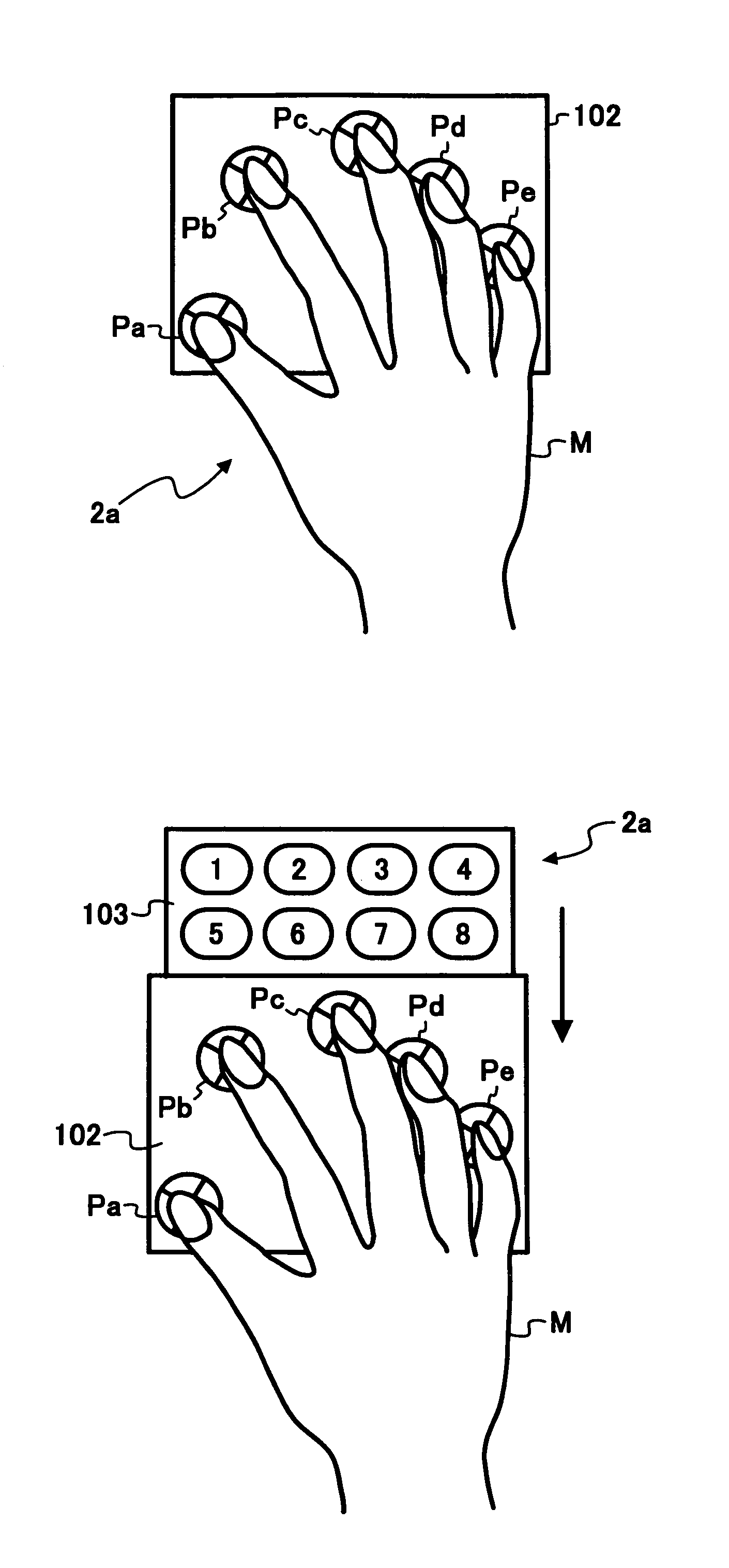
The present invention provides an information input and output system with a display device that can display an icon on the screen for easy operation. The system includes a coordinate input device that detects coordinates on the screen, a storage unit that prestores operation images, and an operation image control unit that displays the operation image at a predetermined position on the screen based on the detected coordinates. The operation image control unit can also distinguish between an operation that indicates multiple positions on the screen and an operation that displays the operation image. The system can also detect movement of the indicated positions on the screen and change the display position or size of the operation image accordingly. The operation image control unit can also display a door image that appears gradually from the lower portion of the screen. The system can also register different kinds of operation images and select the appropriate operation image based on the detected movement. Overall, the invention improves operationality and ease of use of the information input and output system.

Problems solved by technology

Further, in the case where one location on the screen is indicated, the operation image is not displayed, making it possible to easily distinguish between the operation with no object of displaying the operation image (the operation that indicates one location) and the operation that displays the operation image.

Method used


Image

  • Information input and output system, method, storage medium, and carrier wave
  • Information input and output system, method, storage medium, and carrier wave
  • Information input and output system, method, storage medium, and carrier wave

Examples


Embodiment Construction

[0111]An embodiment is specifically described with reference to the drawings attached herewith.

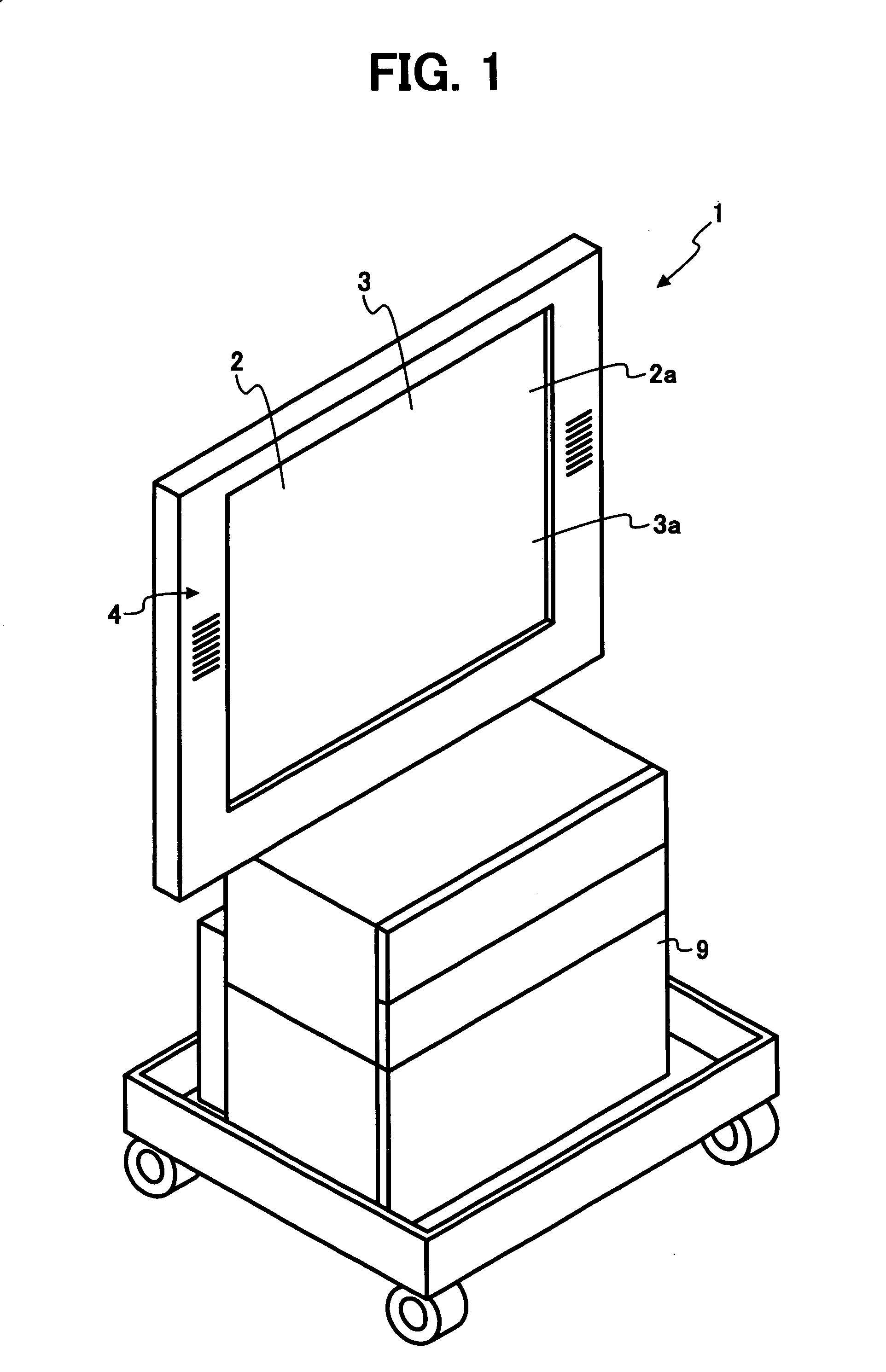
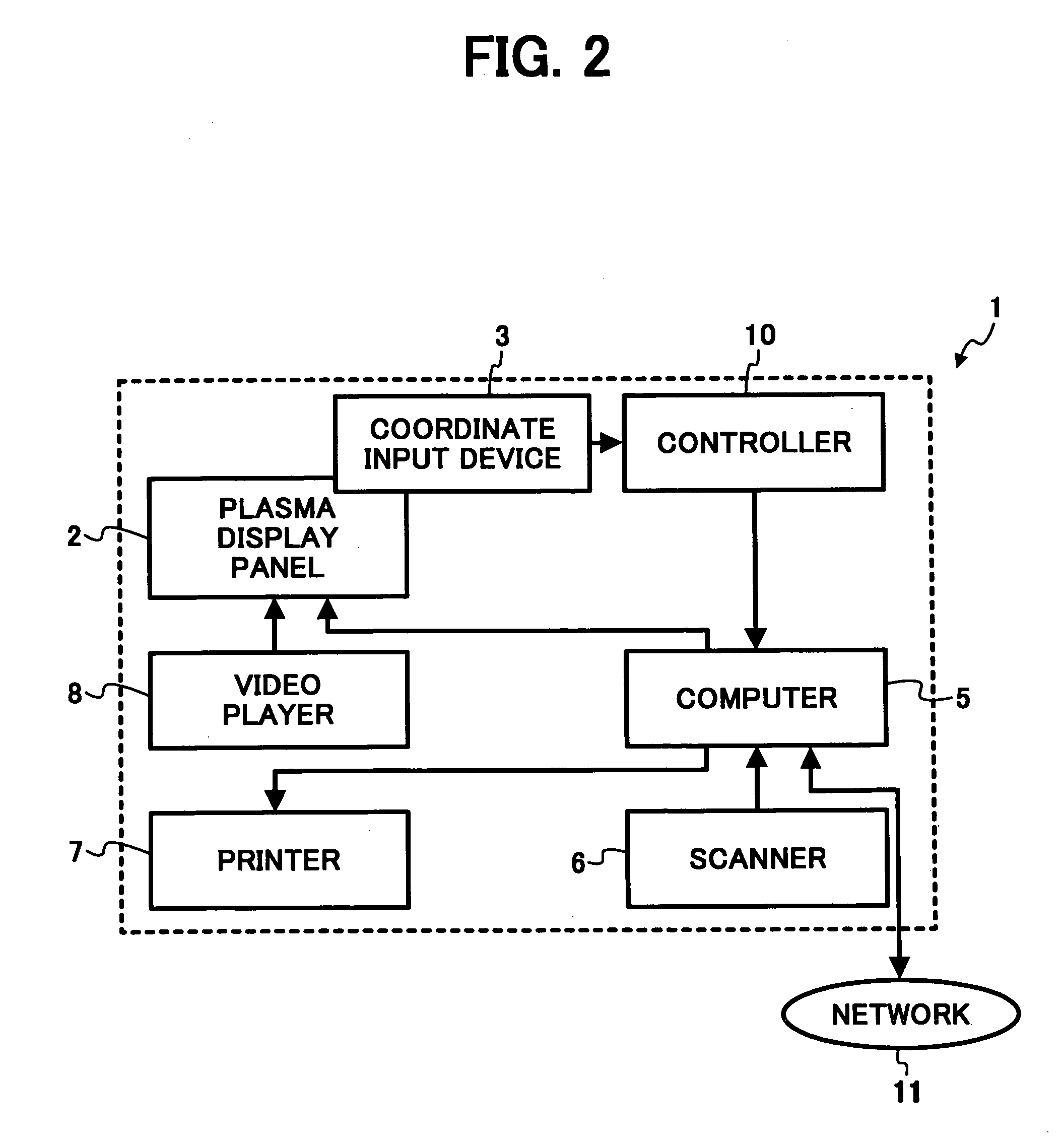
[0112]FIG. 1 is a perspective view schematically showing an information input and output system 1 according to one embodiment of the present invention. FIG. 2 is a block diagram showing an electrical connection of the information input and output system 1. As illustrated in FIGS. 1 and 2, the information input and output system 1 is provided with a panel section 4, a computer 5 such as a personal computer, a scanner 6 that scans an image on an original document, a printer 7 that outputs image data onto a recording paper, and an electronic equipment containing box 9 that contains a video player 8. Additionally, the panel section 4 is an input and output device that is composed of a plasma display panel (PDP) 2, which is a display device, and a coordinate input device 3.

[0113]Any display such as CRT, LCD, and the like may be used as PDP 2 as long as the display is a large screen type of 40 i...


PUM


Abstract

A coordinate input device detects coordinates of a position by indicating a screen of a display device with fingers of one hand, and transfers information of the detected coordinates to a computer through a controller. The computer receives an operation that complies with the detected coordinates, and executes the corresponding processing. For example, when it is detected that two points on the screen have been simultaneously indicated, an icon registered in advance is displayed close to the indicated position.

Description

BACKGROUND OF THE INVENTION[0001]1. Field of the Invention[0002]The present invention relates to an information input and output system that indicates a screen to make it possible to input information using a display device and a coordinate input device.[0003]2. Description of the Related Art[0004]In recent years, there has been provided an information input and output system, which includes a display device that displays characters and images and a coordinate input device that has an information input surface (touch panel surface) on the entire surface of the display device, and a control device that performs display control of the display device based on the input from the coordinate input device, and which constitutes display and writing surfaces of an electronic blackboard using the display device and coordinate input device.[0005]For example, Smart 2000 (made by SMART Technologies Inc.) performs processing for capturing handwritten information into a computer using a coordinate...

Claims


Application Information

Patent Timeline
Patent Type & Authority Patents(United States)
IPC IPC(8): G09G5/00G06F3/041G06F3/042G06F3/048G06F3/0481G06F3/0489G09G5/36
CPCG06F3/03545G06F3/0423G06F3/04883G06F3/04886G06F3/0488G06F2203/04808
Inventor MOROHOSHI, HIROSHI
Owner RICOH KK
Why Eureka
Eureka Blog
Learn More