
Receiving apparatus including adaptive beamformers

a beamformer and receiver technology, applied in the direction of polarisation/directional diversity, instruments, and reradiation, etc., can solve the problems of long delay, high level of mui, waste of bandwidth, etc., and achieve the effect of cost saving

Inactive Publication Date: 2006-03-21
FUJITSU LTD
View PDF9 Cites 25 Cited by
  • Summary
  • Abstract
  • Description
  • Claims
  • Application Information

AI Technical Summary

Benefits of technology

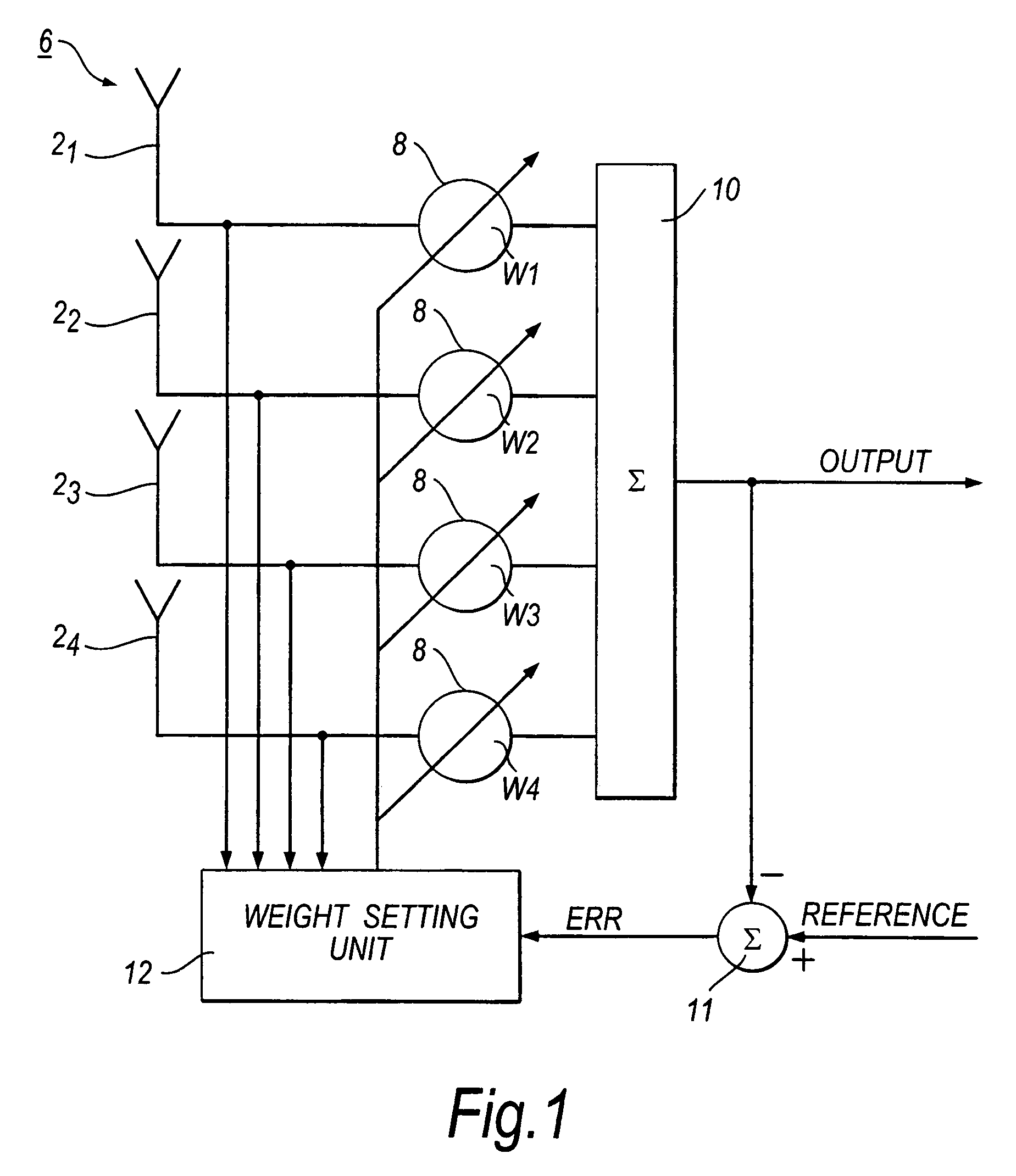
[0016]In receiving apparatus and a receiving method embodying the present invention fast convergence of the beam control information (weight values) for the main beamformer is achieved reliably without the limitations inherent in the above-mentioned two-stage DFT and LMS approach. In particular, the same assistant beamformer can, if desired, be used in serial fashion to form the fixed beams (assistant beam patterns), leading to cost savings. The number of assistant beam patterns can also be greater than the number of antenna elements (received signals). Because each assistant beam pattern is determined by its own individually-corresponding beam control information (weight values) the pointing directions, shapes and widths of the assistant beamformers can be optimally controlled and independently designed according to demand. For example, it may be desired to change the assistant beam patterns from time to time in the course of a 24-hour period to cater for different traffic conditions. Also, each base station site is unique and so it is important to have total freedom in choosing the assistant beam patterns independently of one another. Furthermore, the antenna elements can be unevenly spaced and do not need to be placed uniformly in a single plane.

Problems solved by technology

Thus, it is inappropriate to point the initial beam pattern, which is determined by the initial weight setting of the digital beamformer, to any particular direction.
However, if an omnidirectional initial beam pattern is used, the level of the MUI can be so high that it takes a long time for the adaptation algorithm to converge, which inevitably leads to long delay and / or waste of bandwidth.
However, it suffers from the following serious limitations.
Firstly, it is necessary for all the beams formed during DFT processing to be produced simultaneously, making the hardware construction of the receiving apparatus expensive.
Secondly, the number of fixed beams is limited to being no greater than the number of antenna elements.
Thirdly, there is no control over the beam shapes and pointing directions during the DFT processing.
This lack of control effectively limits the DFT approach to use in switched beam and multi-beam antennas only when the beams are pointed to certain directions and no sidelobe control is needed.
Fourthly, the DFT approach is not fully effective in the case in which two or more of the fixed beams provide comparably-good signals.

Method used


Image

  • Receiving apparatus including adaptive beamformers
  • Receiving apparatus including adaptive beamformers
  • Receiving apparatus including adaptive beamformers

Examples


first embodiment

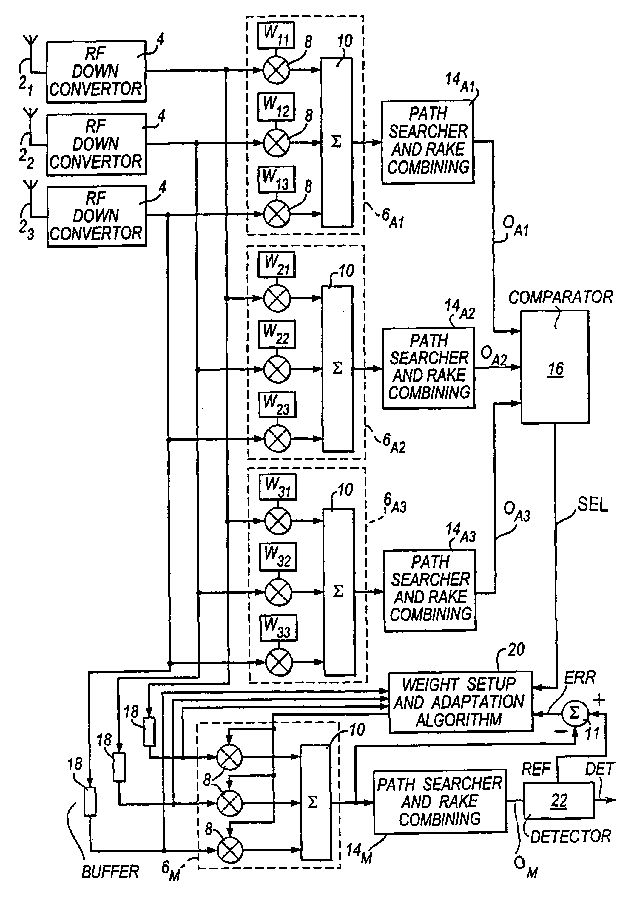
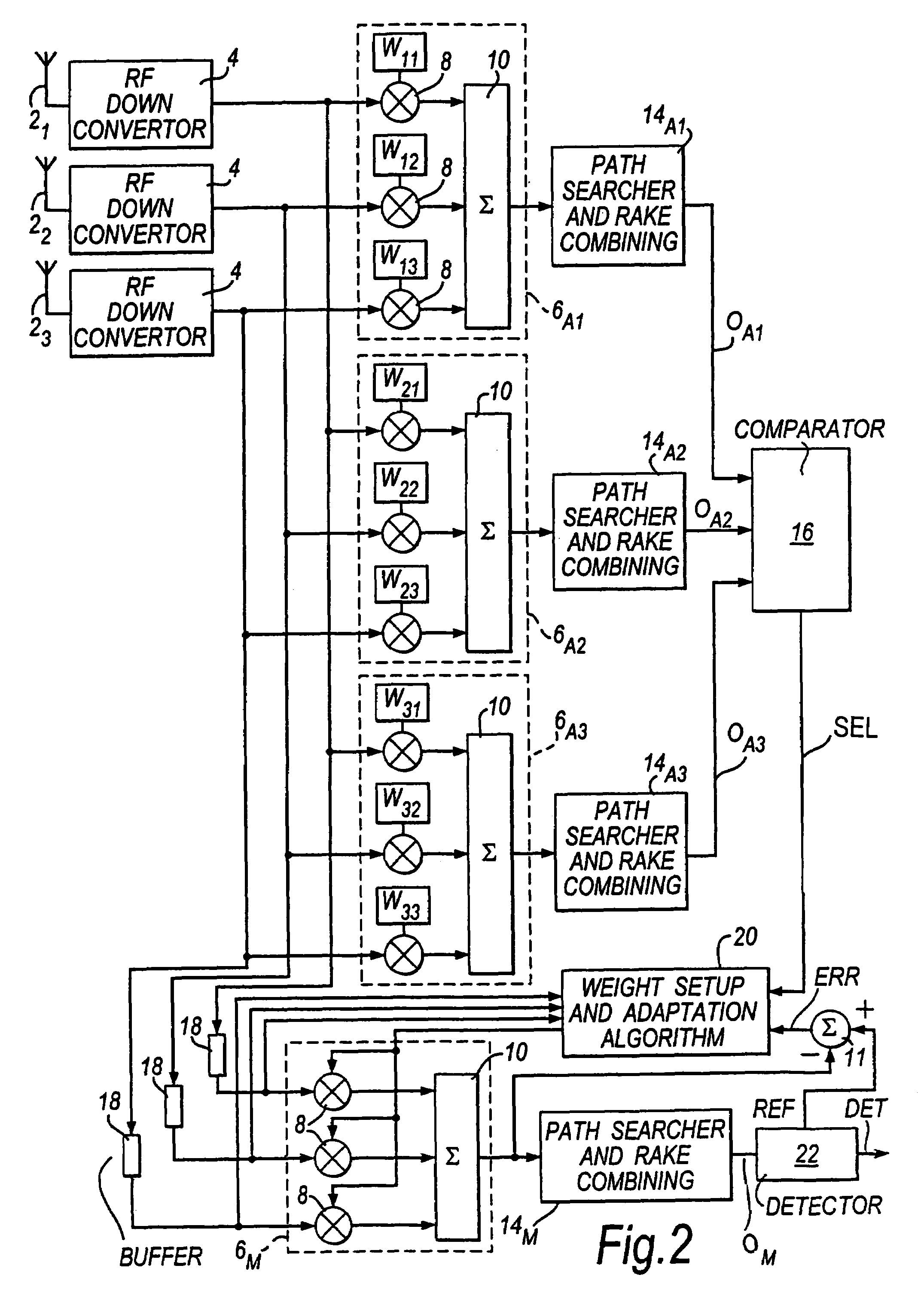
[0028]FIG. 2 shows parts of receiving apparatus according to the present invention. This embodiment is intended for use in a cellular mobile communications system which combines pilot-symbol-assisted modulation (PSAM) with direct-sequence code-division-multiple-access (DS-CDMA). This DS-CDMA PSAM system may, for example, have the following specification:[0029]Modulation method—quadrature phase shift keying (QPSK), pilot-symbol-assisted coherent detection;[0030]Chip rate=4.096 Mchips / s;[0031]Symbol rate=32 kbits / s.

[0032]In such a CDMA system, a pseudo-noise (PN) spreading code is used to spread the transmission signal at the mobile station. This spreading code is known to the receiving apparatus, enabling it to decode (or despread) the spread transmission signal received from the mobile station. Further information on spreading and despreading in DS-CDMA systems can be found, for example, in “CDMA—principles of spread spectrum communications”, Andrew J Viterbi, Addison-Wesley Publish...

third embodiment

[0099]Operation of the third embodiment will now be described with reference to FIG. 8. Initially, each of the switches 34 is configured to select its A1 input and the selection switch 30 is configured to the position shown in FIG. 7 itself which it connects the output of the path searcher and RAKE combiner portion 14 to the input of the control unit 36.

[0100]The sequence of operations is commenced (time A in FIG. 8) when the first pilot-symbol of a batch PS of pilot symbols in the current timeslot at the A1 input of each switch element appears. At this point, the control unit 36 causes the weight settings for the first assistant beamformer to be loaded into the complex number multipliers 8 of the digital beamformer 6. The output signal OA1 of the path searcher and RAKE combiner portion 14 over the period occupied by the batch of pilot symbols is then stored in the control unit 36.

[0101]At the end of the batch PS of pilot symbols (time B in FIG. 8) the control unit 36 loads the weig...


PUM


Abstract

Receiving apparatus, for receiving a transmission signal in a cellular mobile communications system, comprises a main beamformer (6M, 14M) which processes received signals, representing the said transmission signal, in accordance with a main beam pattern. This main beam pattern is determined by beam control information applied to the main beamformer. The main beam pattern is adjusted as necessary during use of the receiving apparatus to facilitate reception of the said transmission signal.The apparatus also has three assistant beamformers (6A1, 14A2; 6A2, 14A2; 6A3, 14A3) that, in an initial operating phase of the apparatus, process such received signals in accordance with three different assistant beam patterns. Each such pattern is determined by beam control information (W1–W33) corresponding individually thereto. The three assistant beamformers produce output signals (OA1, OA2, OA3) corresponding respectively to the different assistant beam patterns.A beam control information setting unit (16, 20) employs the output signals and the beam control information (W11 to W33) corresponding respectively to the said assistant beam patterns to make an initial estimate of the beam control information for the main beamformer.Such receiving apparatus can permit fast setup of the initial beam control information for the main beamformer.

Description

BACKGROUND OF THE INVENTION[0001]1. Field of the Invention[0002]The present invention relates to receiving apparatus including adaptive beamformers. In particular, the present invention can provide receiving apparatus for use in a base station of a cellular mobile communication system.[0003]2. Description of the Related Art[0004]In a cellular mobile communications system, one of the main tasks of the base station is to detect the signal of each wanted user (i.e. each active mobile station) in a multi-user and multi-path environment. In order to achieve satisfactory signal detection at low bit error rates, two conditions must be satisfied. Firstly, the power level of the signal received by the base station from the mobile station must be greater than a certain threshold value. Secondly, the multi-user interference (MUI), sometimes referred to also as multiple access interference (MAI), must be reduced to an acceptable level.[0005]To satisfy the two conditions identified above, it is ...

Claims


Application Information

Patent Timeline
IPC IPC(8): H04B1/69H01Q3/26H04B1/707H04B7/08H04B7/10H04B7/26
CPCH01Q3/26H04B7/0842H01Q3/2605H04B1/7117
Inventor VADGAMA, SUNIL KESHAVJIGUO, YINGJIE JAY
Owner FUJITSU LTD
Learn More