Systems and methods for continuously varying wavelength illumination

a technology of continuous varying wavelengths and wavelengths, applied in the field of precision wavelength illumination selection, can solve the problems of limiting the throughput of such systems, and inability to intuitively understand the average machine vision user's experience, so as to reduce the economic value of the system, limit the throughput, and consume time.

Inactive Publication Date: 2006-03-21
MITUTOYO CORP
View PDF10 Cites 21 Cited by
  • Summary
  • Abstract
  • Description
  • Claims
  • Application Information

AI Technical Summary

Benefits of technology

[0007]The problems associated with using a plurality of light sources or filters involves the initial size, cost and ongoing expense in maintaining the operation of multiple light sources or filters. Also, selecting, balancing and combining such light sources or filters to achieve a particular color or illumination effect is not an intuitive process for the average machine vision user. Also, analyzing such combinations to determine desired illumination, as well as simply accomplishing the physical motions to configure the combinations, is relatively time consuming in comparison to the other operations of a modem high-speed machine vision system, and may easily become the factor that limits the throughput of such systems, thus reducing their economic value. Furthermore, for precision inspection and edge detection, selecting and applying a precise wavelength of illumination may be critical to the accuracy of measurement.
[0008]For application to general purpose commercial machine vision systems, it is highly desirable that the widest possible variety of illumination colors be available for selection. Furthermore, it is desirable that the illumination colors can be configured or selected using a compact, simple and high speed device. Furthermore, it is desirable or necessary that the various image processing methods and illumination methods incorporated into the system can be set up and operated for particular images by relatively unskilled users, that is, users who are not skilled in the field of illumination and image processing. Thus, it is a particular problem to create a machine vision system with which dimensional measurements of specific target features can be performed in a versatile, robust, fast and relatively precise way, while at the same time adapting and governing that machine vision system dimension measurements process through the use of a simple user interface that is operable by a relatively unskilled operator.

Problems solved by technology

The problems associated with using a plurality of light sources or filters involves the initial size, cost and ongoing expense in maintaining the operation of multiple light sources or filters.
Also, selecting, balancing and combining such light sources or filters to achieve a particular color or illumination effect is not an intuitive process for the average machine vision user.
Also, analyzing such combinations to determine desired illumination, as well as simply accomplishing the physical motions to configure the combinations, is relatively time consuming in comparison to the other operations of a modem high-speed machine vision system, and may easily become the factor that limits the throughput of such systems, thus reducing their economic value.
Thus, it is a particular problem to create a machine vision system with which dimensional measurements of specific target features can be performed in a versatile, robust, fast and relatively precise way, while at the same time adapting and governing that machine vision system dimension measurements process through the use of a simple user interface that is operable by a relatively unskilled operator.
Thus, considering the aforementioned problems of full spectrum illumination, multiple colored discrete light sources and the multiple colored discrete filters, conventional methods do not offer reasonable solutions for determining the most desirable illumination setting for measuring specific target features.

Method used


Image

  • Systems and methods for continuously varying wavelength illumination
  • Systems and methods for continuously varying wavelength illumination
  • Systems and methods for continuously varying wavelength illumination

Examples


Embodiment Construction

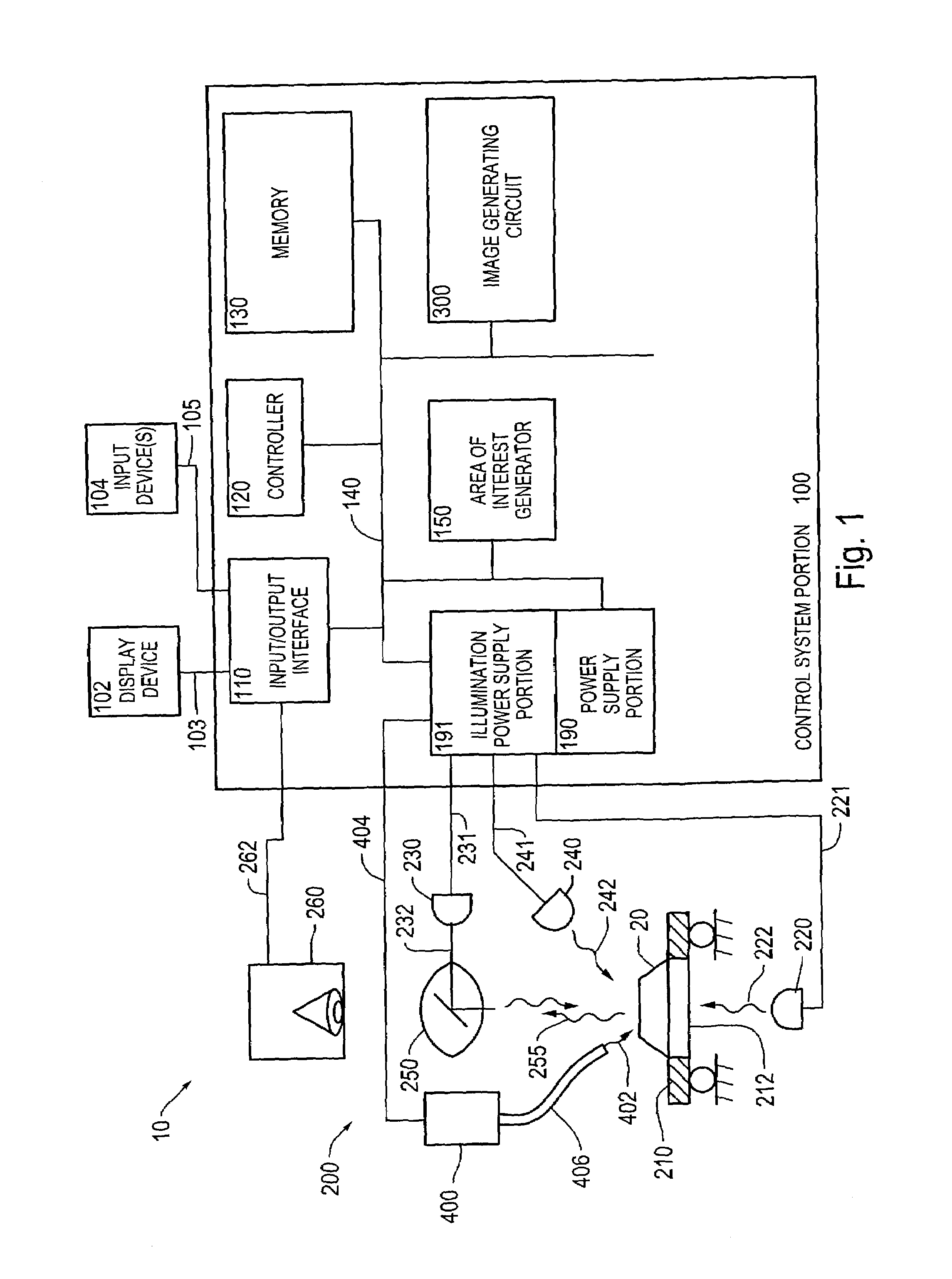
[0030]For simplicity and clarification, the operating principles and design factors of this invention are explained with reference to one exemplary embodiment of a vision system according to this invention, as shown in FIG. 1. The basic explanation of the operation of the vision system shown in FIG. 1 is applicable for the understanding and design of any vision system that incorporates the illumination selection systems and methods according to this invention.

[0031]FIG. 1 shows one exemplary embodiment of a vision system 10 incorporating one exemplary embodiment of the tuned illumination systems and methods according to this invention. As shown in FIG. 1, the vision system 10 includes a control system portion 100 and a vision system components portion 200. The vision system components portion 200 includes a stage 210 having a central transparent portion 212. A workpiece 20 to be imaged using the vision system 10 is placed on the stage 210. One or more of the light sources 220, 230 a...


PUM

PropertyMeasurementUnit
current illumination wavelengthaaaaaaaaaa
illumination wavelengthaaaaaaaaaa
current illumination wavelength control parameteraaaaaaaaaa

Abstract

Systems and methods for operating a vision system to provide a desired illumination wavelength for an inspection operation on workpiece include illuminating a workpiece using narrowband illumination from a continuously variable filter, and modifying the narrowband illumination and evaluating resulting images until a narrowband illumination is found that reliably supports the inspection operation. The initial narrowband illumination may be based on spectral sensing.

Description

BACKGROUND OF THE INVENTION[0001]1. Field of Invention[0002]This invention relates to precision wavelength illumination selection for a machine vision system.[0003]2. Description of Related Art[0004]Conventional machine visions systems perform dimensional measurements of specific target features of a sample workpiece. Such an application is applied, for example, in measuring the position or other characteristic of specific target features of a sample workpiece for comparison to a standard or reference value of the position or other characteristic of the workpiece. In such an application, for different surface colors or color patterns that overlap, appropriate selection of color illumination can enhance the image contrast between different portions of such multi-colored targets. One system for measuring a pattern or feature places a target to be observed on a stage. Thereafter, full spectrum illumination is used by shining a beam of light from a halogen lamp, for example, onto the ta...

Claims


Application Information

Patent Timeline
Patent Type & Authority Patents(United States)
IPC IPC(8): G06K9/00G01B11/00G01N21/01G01N21/27G06T1/00
CPCG06T1/0007
Inventor GLADNICK, PAUL G.
Owner MITUTOYO CORP
Why Eureka
Try Eureka