Hydrokinetic torque converter for an automatic vehicle transmission

a technology of transmission fluid and hydrokinetic torque converter, which is applied in the direction of fluid couplings, gearings, couplings, etc., can solve the problems of increased rejection rate, lack of lubrication oil pressure, and inability to establish a reliable driving connection between the impeller and the gear rotor pump, so as to avoid the damage of the pump element, improve the manufacturing efficiency, and avoid undesirable transmission rejection rates

Active Publication Date: 2006-03-28
FORD GLOBAL TECH LLC
View PDF9 Cites 24 Cited by
  • Summary
  • Abstract
  • Description
  • Claims
  • Application Information

AI Technical Summary

Benefits of technology

[0018]The present invention overcomes the shortcoming of the manufacturing procedure described in the preceding paragraphs by providing a reliable and robust driving connection of the impeller hub shaft with the positive displacement pump wherein the connection comprises registering flats. The invention ensures that external flats formed on the transmission hub are aligned and are fully engaged in registry with internal flats formed on the drive gear of the gear rotor pump when the transmission is assembled to an engine at a vehicle assembly plant or is tested at a test facility in a transmission manufacturing plant.
[0020]When engine crankshaft torque is developed, the impeller hub will rotate relative to the drive gear of the gear rotor pump as the spring force of the drive plate urges the impeller hub shaft toward an engaged position relative to the drive gear of the gear rotor pump. As torque is applied to the impeller, the flat on the drive gear of the gear rotor pump will traverse the ramp on the impeller hub shaft, thereby moving the impeller hub shaft closer to its fully engaged position with respect to the drive gear of the gear rotor pump. This will cause a driving torque to be applied to the pump, which allows the pump to develop an initial control pressure build-up in the transmission control system and in the transmission lubrication oil passages.
[0021]Continued operation of the engine will result in full registry of the flat formed on the drive gear of the gear rotor pump with respect to the flat formed on the impeller hub shaft. When full alignment between the flats is established, the spring force on the drive plate will cause the impeller hub shaft to snap fully into driving registry with respect to the drive gear of the gear rotor pump. Thereafter, the gear rotor pump will operate normally and will be able to develop full control valve circuit pressure and full lubrication oil pressure, which avoids a wear problem for the friction elements of the clutches and brakes, as previously described.
[0022]In addition to the foregoing advantages for quickly developing full circuit pressure during the initial moments of a final powertrain test procedure, the elements of the gear rotor pump itself will be lubricated, thereby avoiding metal-to-metal contact between the pump elements and the wall of the pump chamber in the pump housing. This avoids damage to the pump elements.
[0023]The protection of the moving gear rotor pump elements is another objective of the invention. This feature, together with the feature that protects the friction elements of the transmission clutches and brakes, also improves the manufacturing efficiency in the transmission assembly plant and avoids undesirable transmission rejection rates.
[0024]It is still another objective of the invention to provide a high axial dimensional tolerance at the driving connection between the impeller hub shaft and the drive gear of the gear rotor pump. This will permit axial movement of the impeller hub shaft of the impeller as the impeller housing is rotated by the engine, both during the final testing step of the manufacturing process as well as during subsequent use of the transmission in an automotive vehicle powertrain. This feature will compensate for a so-called ballooning effect for the impeller housing when the converter is rotated at relatively high speeds and a significant centrifugal pressure is developed in the impeller housing. The driving connection established by the registering flats on the impeller hub shaft and on the drive gear of the gear rotor pump will accommodate axial movement on the impeller hub shaft due to the ballooning effect.

Problems solved by technology

If testing were to occur on a transmission at the transmission manufacturing plant when the impeller hub shaft is not indexed properly with respect to the drive gear of the gear rotor pump, again a reliable driving connection between the impeller and the gear rotor pump will not be established because of the out-of-registry condition of the flats on the impeller hub and on the driving gear of the gear rotor pump.
This will cause malfunctioning of the automatic transmission controls and will result as well in a lack of lubrication oil pressure.
This condition can result in a failure of the friction elements of the clutches and brakes, which results in an increased rejection rate and increased manufacturing costs.

Method used


Image

  • Hydrokinetic torque converter for an automatic vehicle transmission
  • Hydrokinetic torque converter for an automatic vehicle transmission
  • Hydrokinetic torque converter for an automatic vehicle transmission

Examples


Embodiment Construction

)

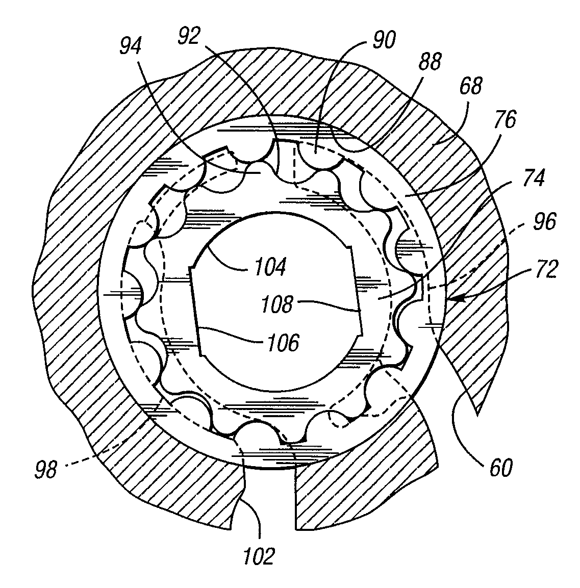
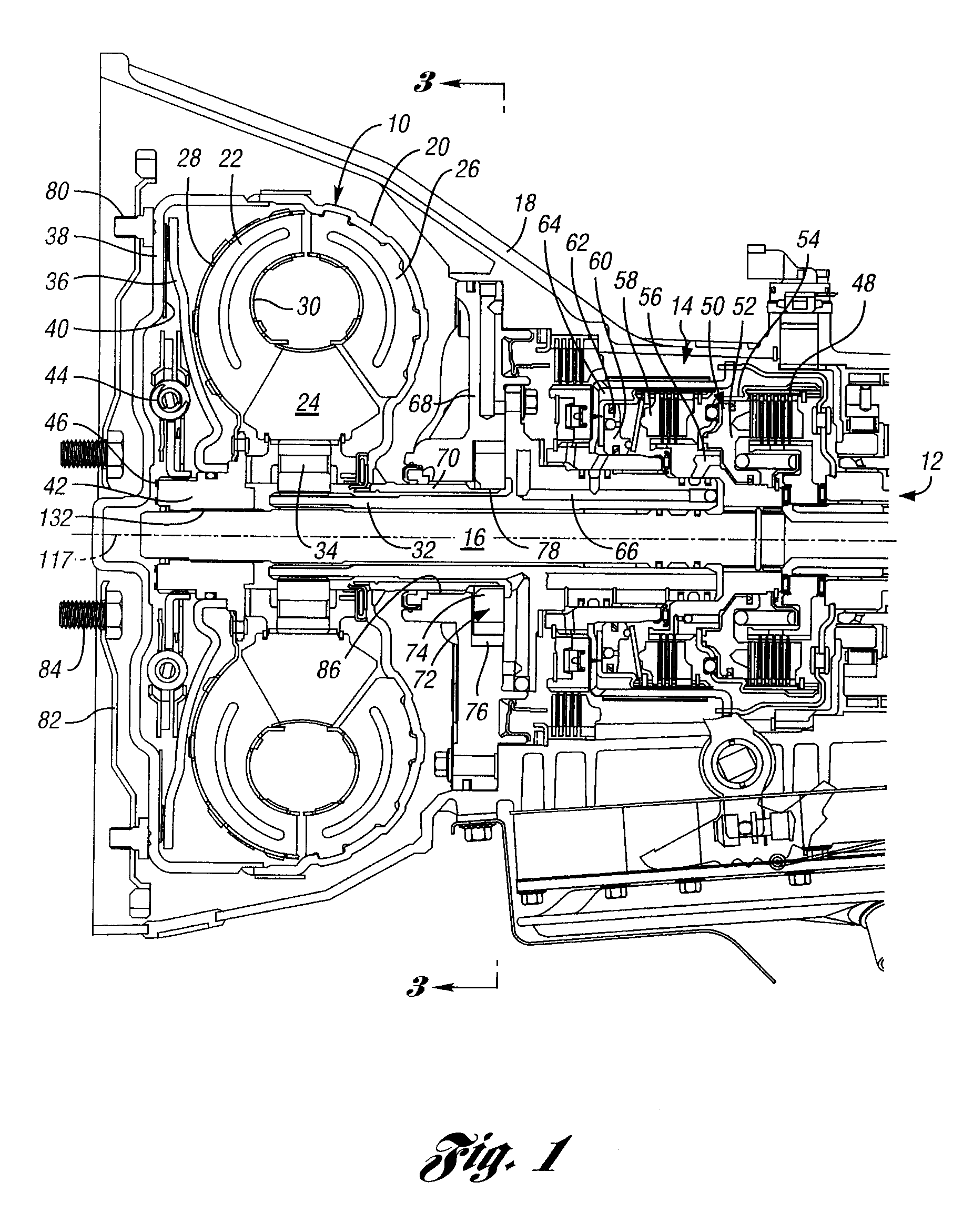
[0033]A torque converter transmission for an automotive vehicle is illustrated partially in cross-section in FIG. 1. It comprises a bladed hydrokinetic torque converter 10, transmission gearing 12, and a friction clutch-and-brake assembly 14 for establishing and disestablishing torque flow paths through the gearing 12 from a torque converter turbine shaft 16. The converter 10, the gearing 12 and the friction clutch-and-brake assembly 14 are situated in a transmission housing 18, which is bolted or otherwise secured to an engine (not shown) in a vehicle powertrain.

[0034]The converter 10 comprises a bladed impeller housing 20, a bladed turbine 22, and a bladed stator 24. The impeller housing 20 encloses turbine 22 and stator 24.

[0035]Impeller blades 26 are secured to the interior of the impeller housing 20. Turbine 22 includes an outer shroud 28 and an inner shroud 30. Turbine blades are secured to the shrouds 28 and 30 in known fashion. The turbine blades and impeller blades 26 defi...


PUM


Abstract

A hydrokinetic torque converter assembly for use with a geared transmission in a vehicle powertrain. The transmission includes a gear pump with a pump driving member and the torque converter assembly includes an impeller shaft drivably engageable with the pump driving member. The impeller shaft and the pump driving member are configured to effect full driving engagement of the impeller shaft with the pump driving member as the torque converter is assembled with the geared transmission.

Description

BACKGROUND OF THE INVENTION[0001]1. Field of the Invention[0002]The invention relates to a hydrokinetic torque converter and a positive displacement transmission fluid pump for an automatic transmission in a vehicle powertrain.[0003]2. Background Art[0004]Automatic transmissions for automotive vehicles may include multiple ratio planetary gearing in a transmission housing that is secured to an internal combustion engine housing. The gearing defines torque flow paths from the engine to a driven shaft of the transmission. The driven shaft is connected drivably to vehicle traction wheels through a suitable driveline and a differential-and-axle assembly. Typically, a hydrokinetic torque converter is situated within the transmission housing at a location intermediate the engine and the multiple ratio gearing.[0005]The hydrokinetic torque converter includes a bladed impeller connected drivably to a crankshaft of an internal combustion engine. The impeller includes an impeller housing that...

Claims


Application Information

Patent Timeline
Patent Type & Authority Patents(United States)
IPC IPC(8): F16D33/00
CPCF16H41/24F16H2045/0294
Inventor CHICKY, JOE
Owner FORD GLOBAL TECH LLC
Why Eureka
Try Eureka