Proximity sensor nozzle shroud with flow curtain

a flow curtain and proximity sensor technology, applied in the field of lithography, can solve the problems of serious shortcomings of sensors, degrade or ruin semiconductor quality, and significant challenges associated with creating proximity sensors of such accuracy, so as to improve the precision of proximity sensors, and reduce the impact of cross winds

Inactive Publication Date: 2006-03-28
ASML HLDG NV
View PDF27 Cites 15 Cited by
  • Summary
  • Abstract
  • Description
  • Claims
  • Application Information

AI Technical Summary

Benefits of technology

[0011]The present invention is directed to an apparatus for reducing the impact of cross winds on gas flow emitted from a nozzle. The apparatus includes a shroud that affixes to the nozzle. A plenum is located inside the shroud that holds a shroud gas, which is fed into the plenum through one or more intake holes. The shroud gas is emitted out through a series of openings, such as holes or slots, along a bottom surface of the shroud in a direction away from the nozzle. The shroud gas that is emitted forms an

Problems solved by technology

The challenges associated with creating a proximity sensor of such accuracy are significant, particularly in the context of photolithography systems.
Occurrence of either situation may significantly degrade or ruin the semiconductor quality.
These proximity sensors have serious shortcomings when used in photolithography systems because physical properties of materials deposited on wafers may impact the precision of these devices.
For example, capacitance gauges, being dependent on the concentration of electric charges, can yield spurious proximity readings in

Method used


Image

  • Proximity sensor nozzle shroud with flow curtain
  • Proximity sensor nozzle shroud with flow curtain
  • Proximity sensor nozzle shroud with flow curtain

Examples


Embodiment Construction

[0018]While the present invention is described herein with reference to illustrative embodiments for particular applications, it should be understood that the invention is not limited thereto. Those skilled in the art with access to the teachings provided herein will recognize additional modifications, applications, and embodiments within the scope thereof and additional fields in which the invention would be of significant utility

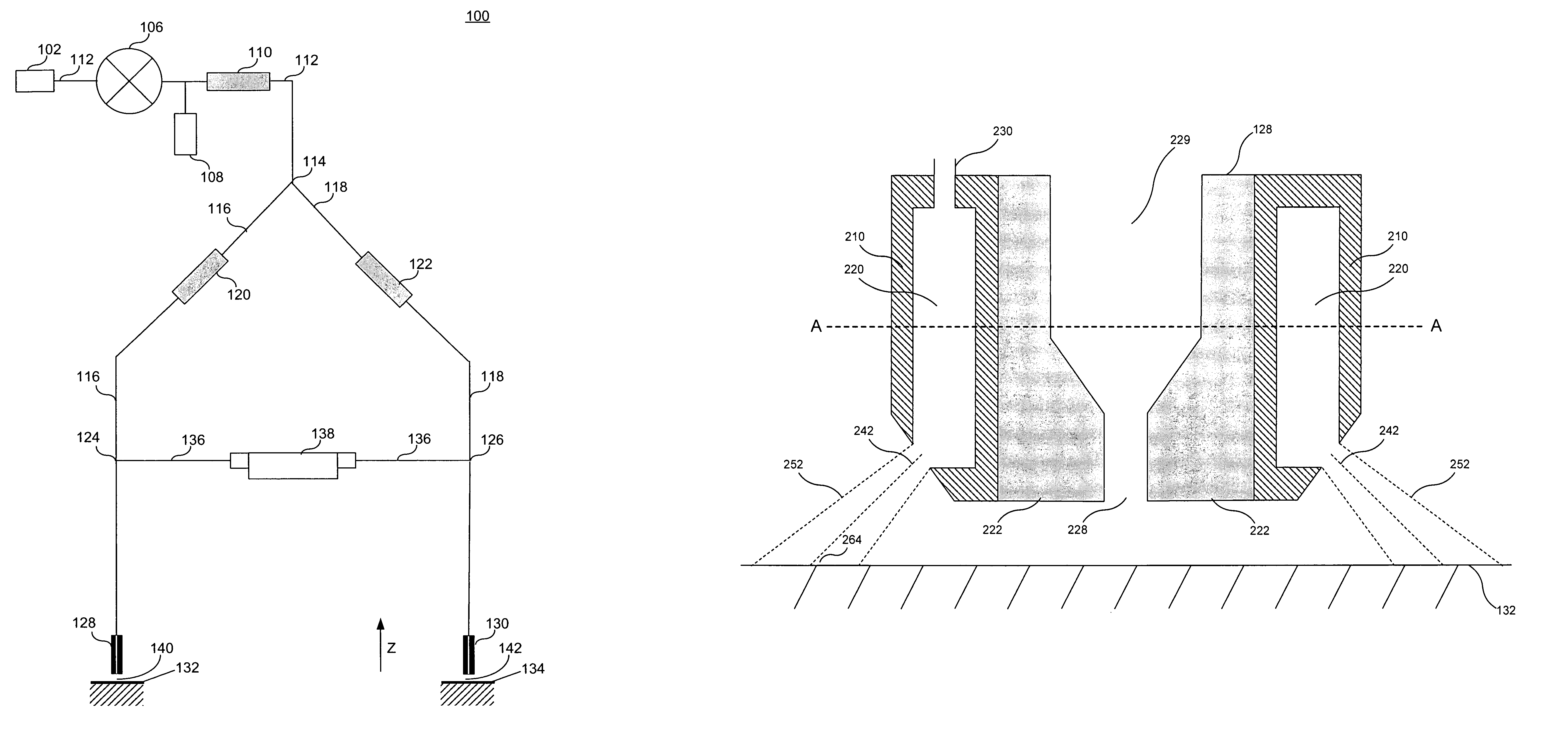
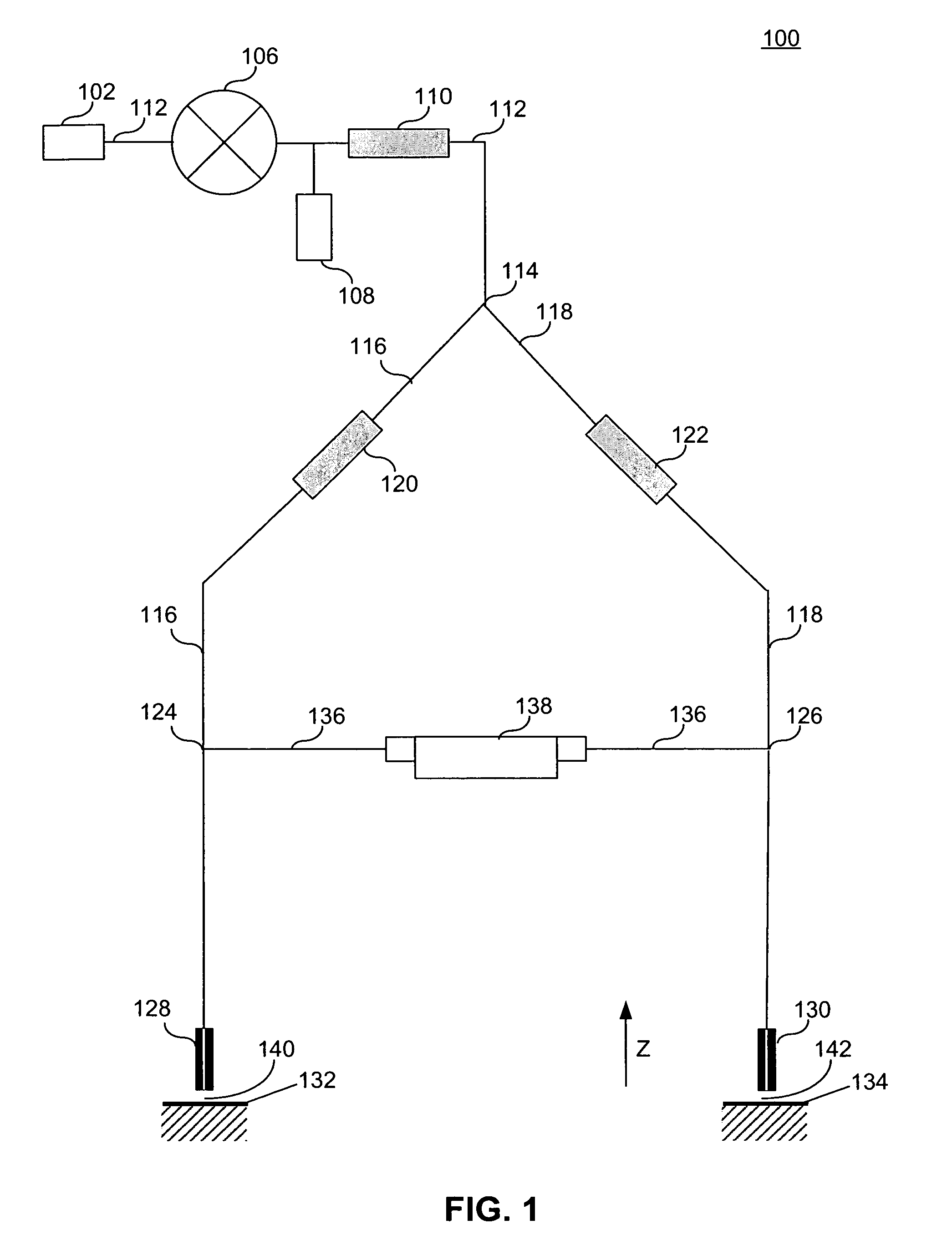
[0019]FIG. 1 illustrates gas gauge proximity sensor 100, according to an embodiment of the present invention. Gas gauge proximity sensor 100 includes mass flow controller 106, central channel 112, measurement channel 116, reference channel 118, measurement channel restrictor 120, reference channel restrictor 122, measurement probe 128, reference probe 130, bridge channel 136 and mass flow sensor 138. Gas supply 102 injects gas at a desired pressure into gas gauge proximity sensor 100.

[0020]Central channel 112 connects gas supply 102 to mass flow controller...


PUM


Abstract

The present invention is directed to an apparatus for reducing the impact of cross winds on gas flow emitted from a nozzle. The apparatus includes a shroud that affixes to the nozzle. A plenum is located inside the shroud that holds a shroud gas, which is fed into the plenum through one or more intake holes. The shroud gas is emitted out through a series of openings, such as holes or slots, along a bottom surface of the shroud in a direction away from the nozzle. The shroud gas that is emitted forms an air curtain around the nozzle to prevent cross winds from impacting the flow of gas out of the nozzle. In one application, the apparatus is used with a lithography gas gauge proximity sensor. The apparatus can also be used with nozzles that emit liquids, such as, for example, an immersion lithography proximity sensor.

Description

BACKGROUND OF THE INVENTION[0001]1. Field of the Invention[0002]The present invention relates to lithography, and more particularly, to lithography gas gauges.[0003]2. Background of Invention[0004]Many automated manufacturing processes require the sensing of the distance between a manufacturing tool and the product or material surface being worked. In some situations, such as semiconductor lithography, the distance must be measured with accuracy approaching a nanometer.[0005]The challenges associated with creating a proximity sensor of such accuracy are significant, particularly in the context of photolithography systems. In the photolithography context, in addition to being non-intrusive and having the ability to precisely detect very small distances, the proximity sensor can not introduce contaminants or come in contact with the work surface, typically a semiconductor wafer. Occurrence of either situation may significantly degrade or ruin the semiconductor quality.[0006]Different ...

Claims


Application Information

Patent Timeline
IPC IPC(8): G01B13/08
CPCG03F7/70341G03F9/7023G03F7/70933
Inventor VOGEL, HERMAN
Owner ASML HLDG NV
Why Eureka
Try Eureka