Woodworking tension board

a tension board and wood technology, applied in the direction of metal-working machine components, metal working apparatus, manufacturing tools, etc., can solve the problems of not being able to move the stock in both directions, the tension board presently available is believed to be less than optimal in a number of respects, and the least not readily available devices, so as to avoid deficiencies

Inactive Publication Date: 2006-03-28
CODERRE MARCEL
View PDF10 Cites 20 Cited by
  • Summary
  • Abstract
  • Description
  • Claims
  • Application Information

AI Technical Summary

Benefits of technology

[0004]While some of these disadvantages may be ameliorated by rounding of contact elements, it is the broad object of the present invention to provide a novel woodworking tension board that avoids deficiencies of the prior art devices and that may, at the same time, provide the advantages thereof.
[0005]More specific objects of the invention are to provide a tension board that readily permits lifting of the workpiece and movement in opposite directions, that is highly tolerant of misalignment relative to the workpiece and / or the cutting machine fence, that accommodates tapered workpieces, and that affords ready and effective selection and control of applied, uniform tension.

Problems solved by technology

Despite widespread use, tension boards presently available are believed to be less than optimal in a number of respects.
In particular, no presently known device permits movement of the stock in both directions, or at least not readily so.
Moreover, the featherboard is not very tolerant of misalignment, it tends to mar the contacted edge of the workpiece (particularly if it is lifted from the table surface), it does not accommodate tapered workpieces, and it does not produce a uniform level of tension along its length or enable significant variation of the level of tension applied to the workpiece.

Method used


Image

  • Woodworking tension board
  • Woodworking tension board
  • Woodworking tension board

Examples


Embodiment Construction

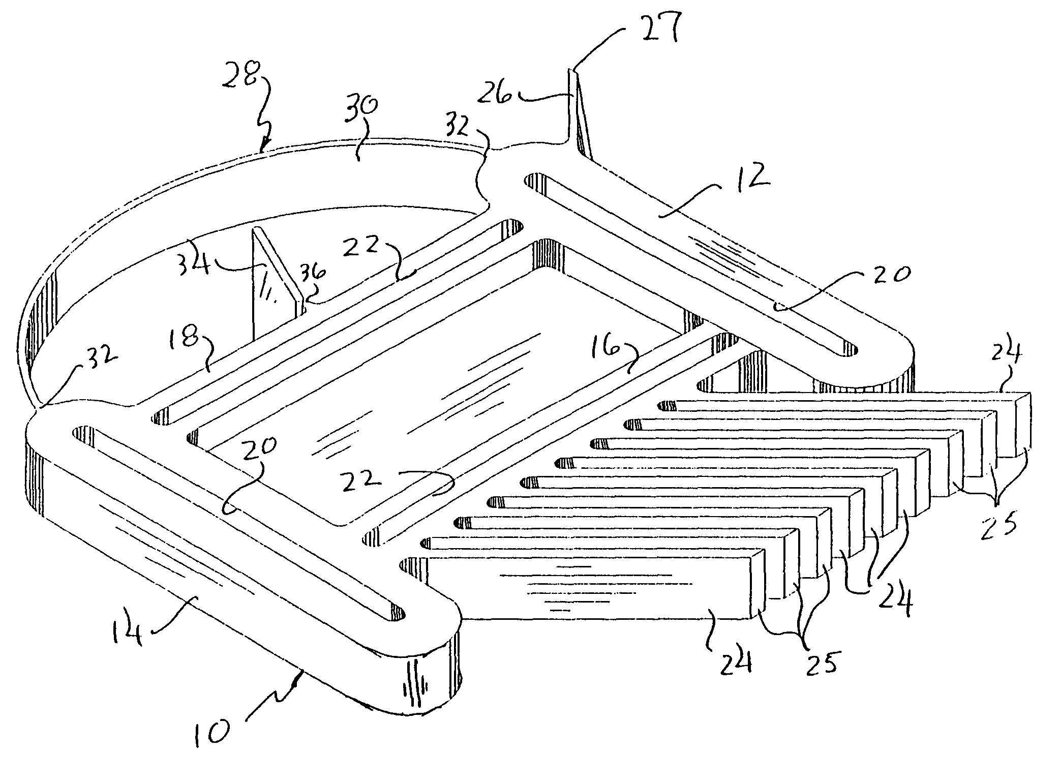
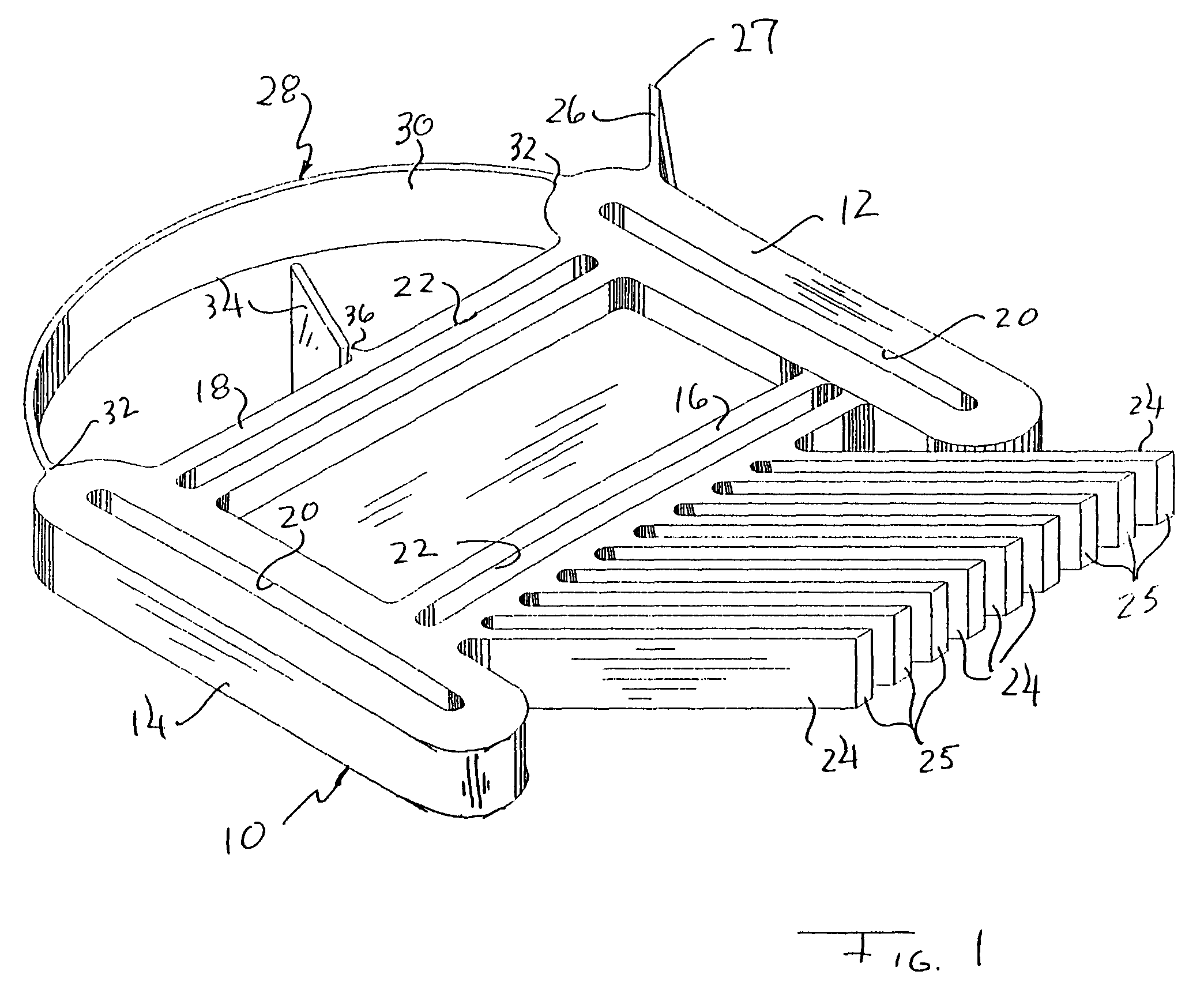
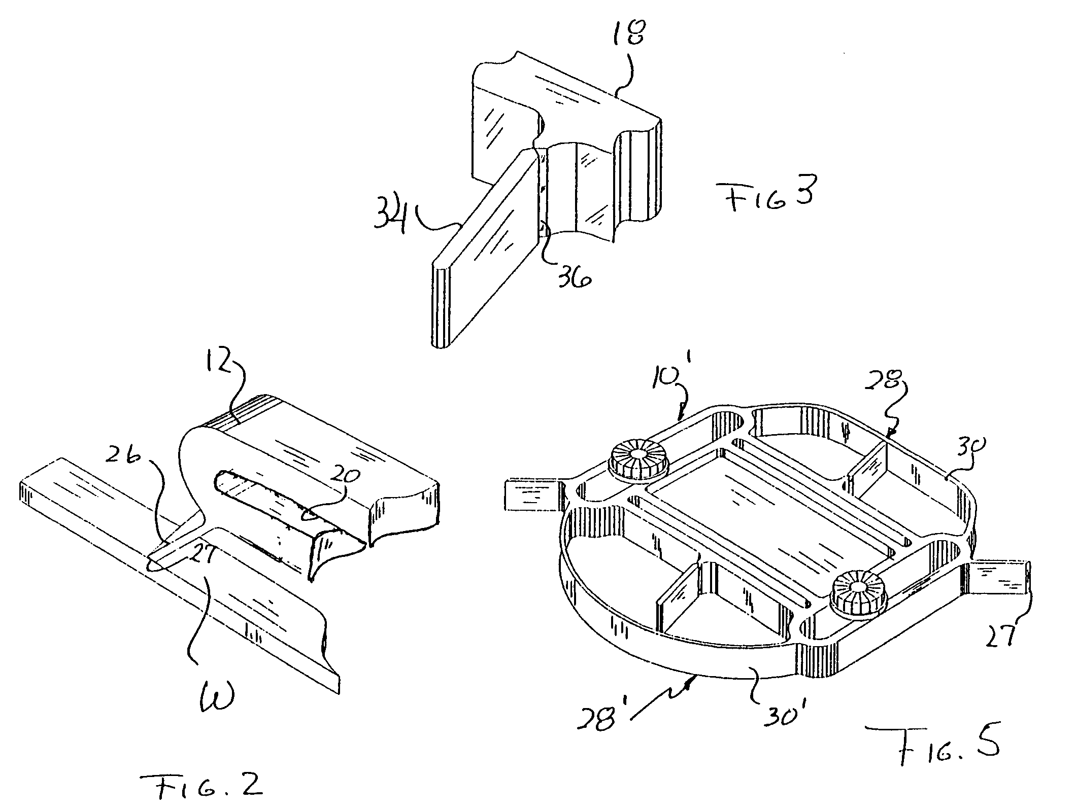
[0017]Turning now in detail to FIGS. 1 through 3 of the drawings, therein illustrated is a combination tension board embodying the present invention and consisting of a body, generally designated by the numeral 10, having laterally opposite arm portions 12 and 14 and transversely opposite marginal edge portions 16 and 18. The arm portions 12, 14 are slotted at 20, as are the marginal edge portions 16, 18 at 22; albeit other slot arrangements and orientations (e.g., oblique) can be employed, in this embodiment the slots 20 are mutually parallel and are perpendicular to the mutually parallel slots 22.

[0018]Nine parallel fingers, or feathers, 24 project, at an acute included angle, from the marginal edge portion 16 of the body 10, and are formed with flat tips 25 disposed on a common plane lying parallel to the slots 22. A single small finger 26 extends from the arm 12, and also terminates in a flat contact surface 27.

[0019]An arcuate bow component, generally designated by the numeral ...


PUM

PropertyMeasurementUnit
tensionaaaaaaaaaa
forceaaaaaaaaaa
rigidityaaaaaaaaaa

Abstract

A tension board comprises a bow member that can deform resiliently to apply lateral force to a workpiece pushed between it and the fence of a table saw, and that may have an associated tension gauge element. Combination tools may employ two bow members having different force-generating characteristics, an array of feather members, and a single contact finger.

Description

BACKGROUND OF THE INVENTION[0001]So-called “tension boards” are commonly used to assist in guiding a workpiece through a table saw, router, shaper, or like woodworking machine, and are well know in the art (see for example, Graham U.S. Pat. No. 2,525,894 and Starnes U.S. Pat. No. 2,699,804). The primary function of such a tool is to maintain lateral force upon a workpiece as it is moved along upright fence structure, albeit the device may also be used to apply downward force for maintaining the workpiece against the table surface.[0002]A commercially available tension board, or featherboard, is described in Morris U.S. Pat. No. 4,476,757. It consists of a body having an array of angularly extending, parallel resilient fingers, and two transverse slots. In use, the body of the featherboard is positioned laterally on an expansion bar, slidably seated in a groove of the machine table, to dispose the free ends of the fingers a suitable distance away from the rip fence (i.e., slightly le...

Claims


Application Information

Patent Timeline
Patent Type & Authority Patents(United States)
IPC IPC(8): B26D7/06B23Q3/00
CPCB23Q3/002Y10T83/741Y10T83/745Y10T83/6576Y10T83/888Y10T83/73Y10T83/773
Inventor CODERRE, MARCEL
Owner CODERRE MARCEL
Why Eureka
Try Eureka