Fuel supply device of an internal combustion engine

a fuel supply device and internal combustion engine technology, applied in the direction of electrical control, process and machine control, instruments, etc., can solve the problem of reducing the fed quantity of fuel, and achieve the effect of reducing the driving torque of the fuel pump, improving the precision of force fed fuel, and reducing energy consumption

Active Publication Date: 2006-03-28
DENSO CORP
View PDF14 Cites 5 Cited by
  • Summary
  • Abstract
  • Description
  • Claims
  • Application Information

AI Technical Summary

Benefits of technology

[0006]In the aforementioned common-rail type internal combustion engine, improvement of the precision of the force fed fuel, reduction of the driving torque of the fuel pump as a load on the output of the internal combustion engine, and reduction of energy consumption are demanded. In order to achieve these, improvement of the structure of the fuel supply device has been made earnestly.
[0007]The present invention was made in view of the circumstances described above. It is an object of the present invention to provide a fuel supply device of an internal combustion engine that can easily reduce a driving torque and energy consumption by devising a control over the fuel supply device, not by improving the structure of the fuel supply device itself.
[0010]In a contraction process in which the volume of the pressure chamber of the fuel pump is contracted, the contraction rate has a peak in the latter half of the contraction process. At this peak, the driving torque is also larger. In the thinned-out control, for a part of the pressure chambers, the force fed fuel is thinned out. The pressure chamber for which the force fed fuel is not thinned out is burdened with the thus thinned out feed. With the increase of the burden, in the pressure chamber for which the force fed fuel is not thinned out, the closing time of the opening / closing valve is put ahead. Thus, part of the force fed fuel can be preformed in a period in which the driving torque is relatively smaller, not in a period in which the driving torque is larger. On the other hand, in the pressure chamber for which the force fed fuel is thinned out, the driving torque is substantially zero. Therefore, the driving torque of the fuel supply device can be reduced.
[0011]Moreover, it is also possible to reduce the operation frequency of the opening / closing valve. Therefore, the energy consumption of the fuel supply device can be reduced, and the life thereof can be made longer.
[0013]It is possible to smoothly perform the switching from the normal control to the thinned-out control.
[0015]It is possible to smoothly perform the switch from the thinned-out control to the normal control.

Problems solved by technology

On the other hand, delaying the closing time so as to seal the fuel in the pressure chamber when the volume of the pressure chamber is small reduces the fed quantity of fuel.

Method used


Image

  • Fuel supply device of an internal combustion engine
  • Fuel supply device of an internal combustion engine
  • Fuel supply device of an internal combustion engine

Examples


Embodiment Construction

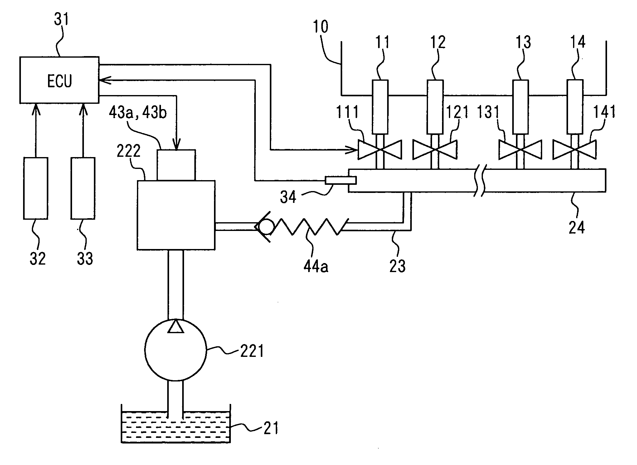
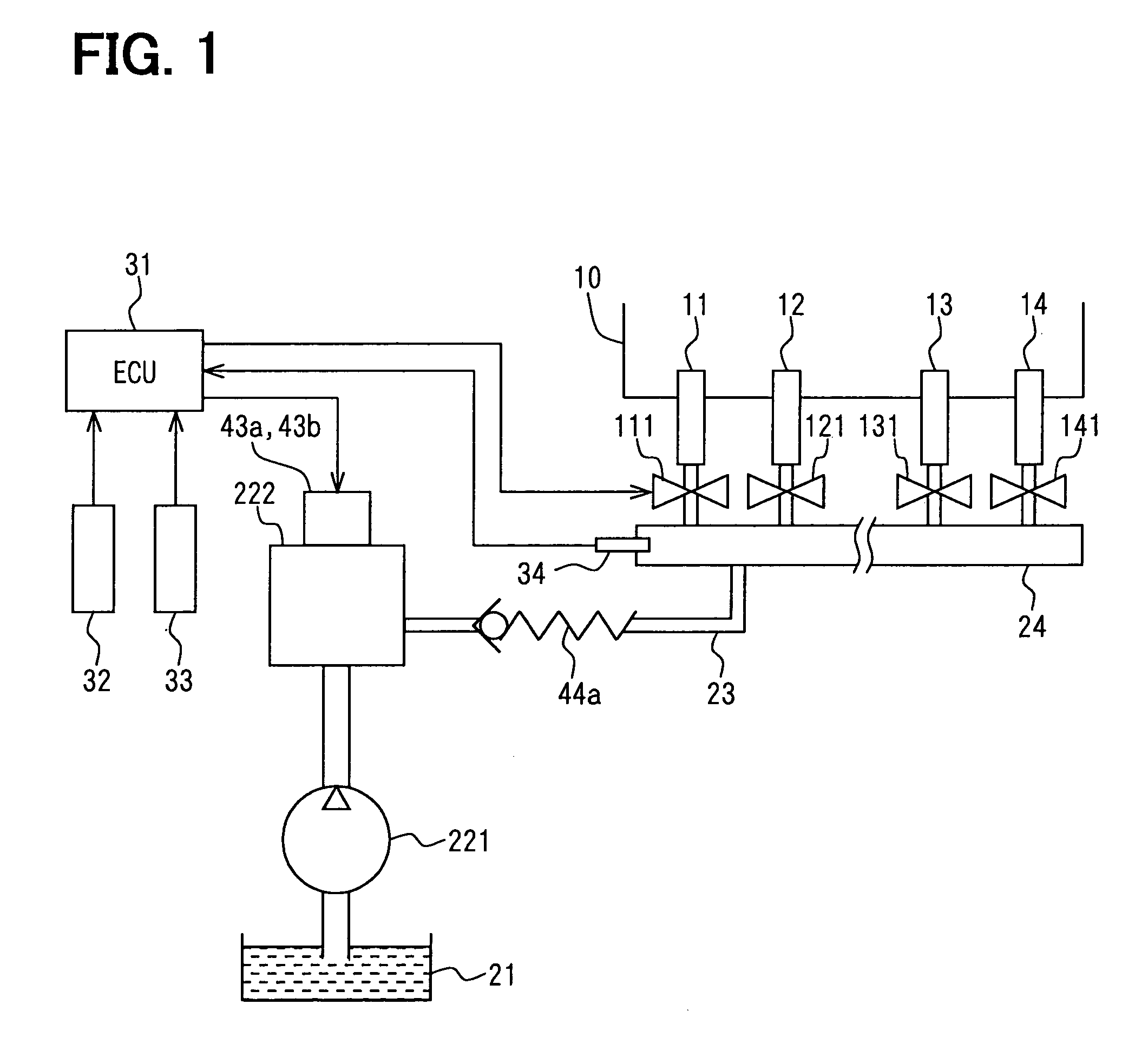
[0026]FIG. 1 shows the structure of a diesel engine (hereinafter, simply referred to as engine) as a contraction-ignition type internal combustion engine to which a fuel supply device of the present invention is applied. This embodiment is described on the assumption that the engine is mounted on a vehicle. An engine body 10 includes a plurality of cylinders. Injectors 11, 12, 13, and 14 are provided to correspond to the cylinders of the engine body 10 in one-to-one correspondence. Each of the injectors 11, 12, 13, and 14 is opened and sprays fuel at a predetermined time for a predetermined period by control of an ECU 31. The injectors 11, 12, 13, and 14 are opened by electromagnetic valves 111, 121, 131, and 141 provided for the injectors 11, 12, 13, and 14, respectively. Fuel is injected during a period approximately corresponding to the period in which each electromagnetic valve is driven. The engine body 10 has a typical structure and also includes a component that is not shown,...


PUM


Abstract

A fuel supply device includes a fuel pump, a plurality of valves, and a controller. The fuel pump includes a plurality of pressure chambers each having a volume that is expanded and contracted by the engine. The plurality of valves open and close the pressure chambers. An expansion time and a contraction time of the pressure chambers are each different. The fuel pump is operable to sealingly store fuel in the pressure chambers by closing the valves. The controller sets closing times for the valves in accordance with a required quantity of fuel to be force fed. The controller switches between a normal control in which all of the pressure chambers sequentially force feed fuel and a thinned-out control in which the force fed fuel is thinned out by stopping closing at least one of the valves.

Description

CROSS REFERENCE TO RELATED APPLICATIONS[0001]This application is based upon and claims the benefit of priority of Japanese Patent Application No. 2004-14377, filed on Jan. 22, 2004, the contents of which are incorporated herein by reference.FIELD OF THE INVENTION[0002]The present invention relates to a fuel supply device of an internal combustion engine.BACKGROUND OF THE INVENTION[0003]A typical fuel supply device of an internal combustion engine mounted in a vehicle includes a fuel pump. In the fuel supply device, fuel is pressurized and a mist is sprayed via an injector. In recent years, a common-rail type internal combustion engine having a common rail for storing fuel to be supplied to the injector that has been pressurized in advance is widely known. In this type of internal combustion engine, the fuel is forced from the fuel pump to the common rail. Such fuel supply devices are disclosed Laid-Open Japanese Patent Application Publication No. 9-222056 and Laid-Open Japanese Pate...

Claims


Application Information

Patent Timeline
Patent Type & Authority Patents(United States)
IPC IPC(8): F02M37/04B60K31/00F02D33/00F02D41/04F02M37/00F02M59/08F02M59/20F02M59/36
CPCF02D33/003F02D41/08F02D41/3845F02M37/0047F02M59/102F02M59/366F02M63/028F02M59/04F02M2200/03F02M63/0225
Inventor WANG, XIUMEI
Owner DENSO CORP
Why Eureka
Try Eureka