Stackable low depth tray

a low-depth, tray technology, applied in the direction of tray containers, internal fittings, transportation and packaging, etc., can solve the problems of bottle buckles, stacking falling, undetectable low limit on the number of tiers, etc., to achieve greater support and stability of the loaded bottles, high strength, and high visibility of bottles

Inactive Publication Date: 2006-03-28
REHRIG PACIFIC CO INC
View PDF170 Cites 66 Cited by
  • Summary
  • Abstract
  • Description
  • Claims
  • Application Information

AI Technical Summary

Benefits of technology

[0011]It is another object according to the present invention to provide a low depth tray for bottles that is structured for high strength as well as high visibility of the bottles contained therein.
[0012]It is yet another object according to the present invention to provide a low depth tray for bottles that provides greater support and stability of the bottles loaded in the tray.
[0013]It is another object according to the present invention to provide a low depth tray for bottles which is lightweight and easy to handle.
[0014]It is another object according to the present invention to provide a low depth tray for bottles that is easier and less expensive to manufacture.

Problems solved by technology

However, if a compressive load is applied to a conventional PET beverage bottle along a direction other than the symmetry axis of the bottle, the bottle may buckle, particularly for large capacity bottles such as the two-liter bottle widely used for marketing soft drinks.
Tilted bottles in the lower trays of a stack can buckle, causing the stack to fall.
Even absent buckling, the tendency of bottles to tilt in conventional low-sided trays causes instability and places an undesirably low limit on the number of tiers that can be included in a stack.
While some trays may partially fulfill these objectives, two important problems are encountered with current low depth trays.
Second, the wall structure of current trays often requires a snug fit between the bottle pocket and the bottle to ensure stability, which limits the range of bottle diameters which can be retained in a stable stack.

Method used


Image

  • Stackable low depth tray
  • Stackable low depth tray
  • Stackable low depth tray

Examples


Embodiment Construction

)

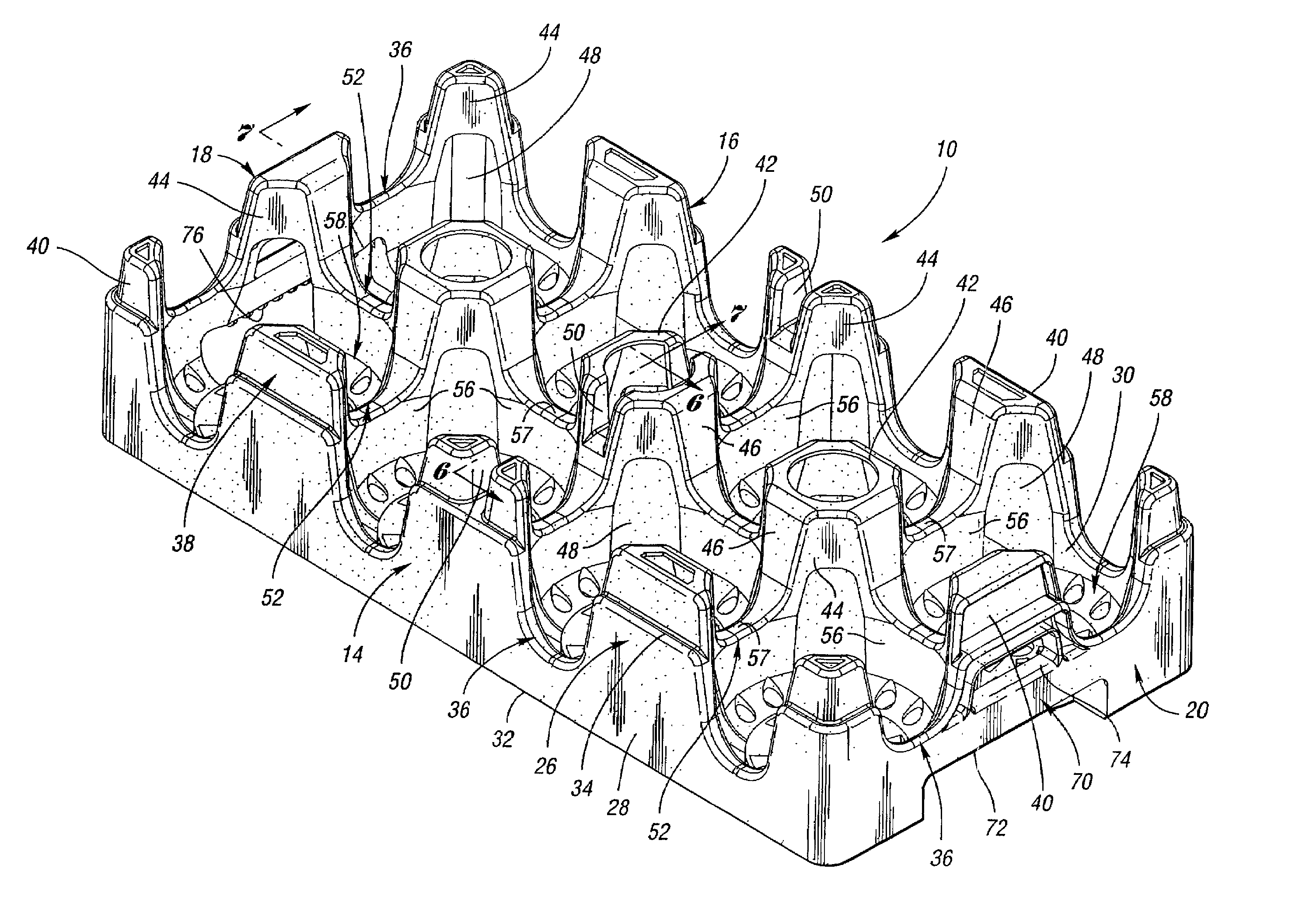
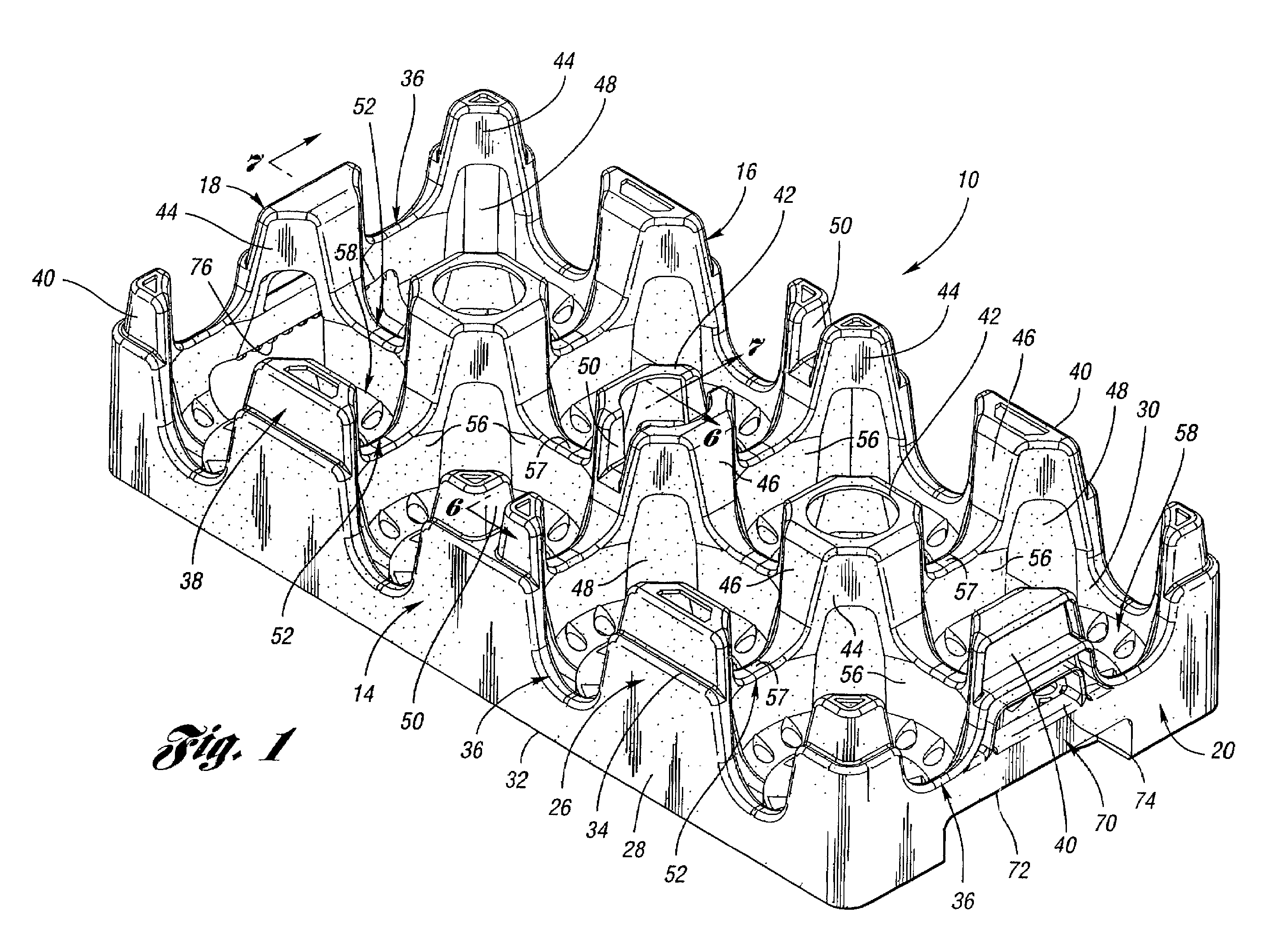
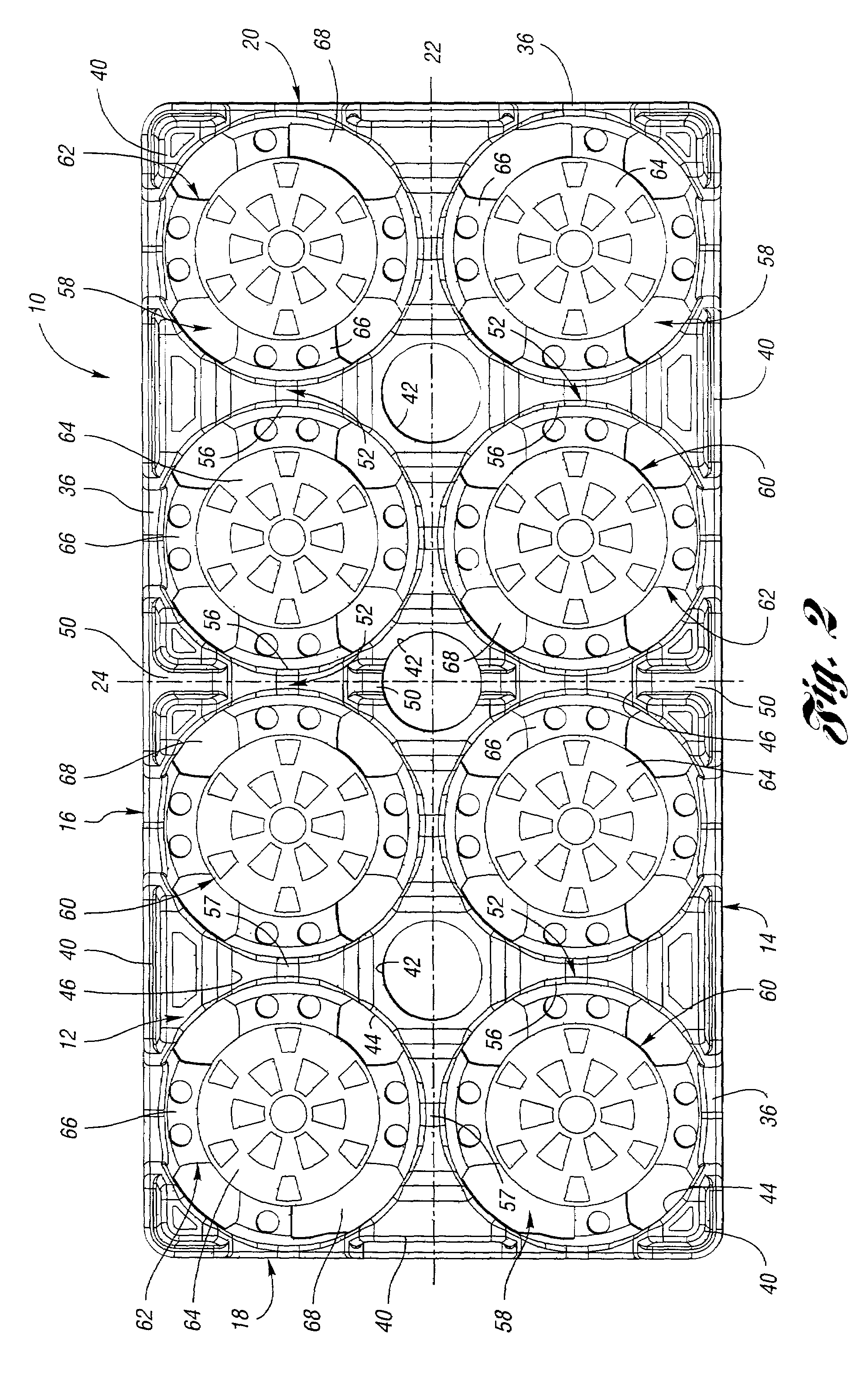
[0039]FIGS. 1–5 show several views of a low depth tray 10 according to the present invention. While tray 10 is suited for many uses, tray 10 is particularly suitable for storing and transporting bottles B (see FIGS. 10, 13, and 15). Tray 10 includes a base 12 or floor member (best shown in FIGS. 2–3), a first pair of opposed walls 14, 16, and a second pair of opposed walls 18, 20. For convenience, and without additional limitation, first pair of opposed walls 14, 16 will be referred to herein as side walls, and second pair of opposed walls 18, 20 will be referred to herein as end walls. Side walls 14, 16 and end walls 18, 20 are attached to each other to form a wall structure, and are attached to base 12 and extend upwardly therefrom. Preferably, side walls 14, 16, end walls 18, 20, and base 12 form an integral, unitary member of one-piece construction. Tray 10 is generally symmetric about a longitudinal axis 22 and a transverse axis 24 thereof (see FIG. 2).

[0040]Tray 10 is typical...


PUM


Abstract

A low depth tray for bottles is provided which includes a first pair of opposed walls, a second pair of opposed walls attached to the first pair of opposed walls to form a wall structure, and a base attached to the wall structure. At least one interior column projects upwardly within the wall structure, where the interior column has a height less than the height of bottles loaded in the tray. A plurality of interior divider walls of double-walled construction project upwardly from the base and extend between the one or more interior columns and the wall structure. Together, the divider walls, interior columns, base, and outer wall structure define a plurality of bottle retaining pockets, where each pocket includes at least one divider wall and is sized to receive a single bottle therein.

Description

BACKGROUND OF THE INVENTION[0001]1. Field of the Invention[0002]This invention relates to a stackable low depth tray for storing and transporting beverage containers, such as bottles.[0003]2. Background Art[0004]Bottles, particularly for soft drinks and other beverages, are often stored and transported in trays. The term “tray” as used herein includes trays, crates, cases, and similar containers having a floor and a peripheral side wall structure. As compared with other materials, plastic trays provide advantages such as strength, durability, and reusability. In order to minimize the storage space of trays, reduce their cost and weight, and promote display of the bottles contained therein, many trays are constructed to have shallow side and end walls. Such trays are generally referred to as “low depth” trays in which the side and end walls are lower than the height of the stored bottles, and in which the bottles support the weight of additional trays stacked on top.[0005]In general,...

Claims


Application Information

Patent Timeline
Patent Type & Authority Patents(United States)
IPC IPC(8): B65D1/36B65D21/02B65D25/10B65D25/30
CPCB65D1/243B65D71/70B65D2501/24019B65D2501/24108B65D2501/24127B65D2501/24687B65D2501/24222B65D2501/24254B65D2501/2435B65D2501/24509B65D2501/24152B65D1/36B65D21/0212B65D71/0003
Inventor APPS, WILLIAM P.
Owner REHRIG PACIFIC CO INC
Why Eureka
Try Eureka