Swashplate pump

a technology of swashplate pump and swashplate, which is applied in the direction of machine/engine, positive displacement liquid engine, gearing, etc., can solve the problems of various drawbacks of each of these approaches

Active Publication Date: 2006-03-28
WAGNER SPRAY TECH CORP
View PDF13 Cites 20 Cited by
  • Summary
  • Abstract
  • Description
  • Claims
  • Application Information

AI Technical Summary

Problems solved by technology

Each of these approaches have suffered from v

Method used


Image

  • Swashplate pump
  • Swashplate pump
  • Swashplate pump

Examples


Embodiment Construction

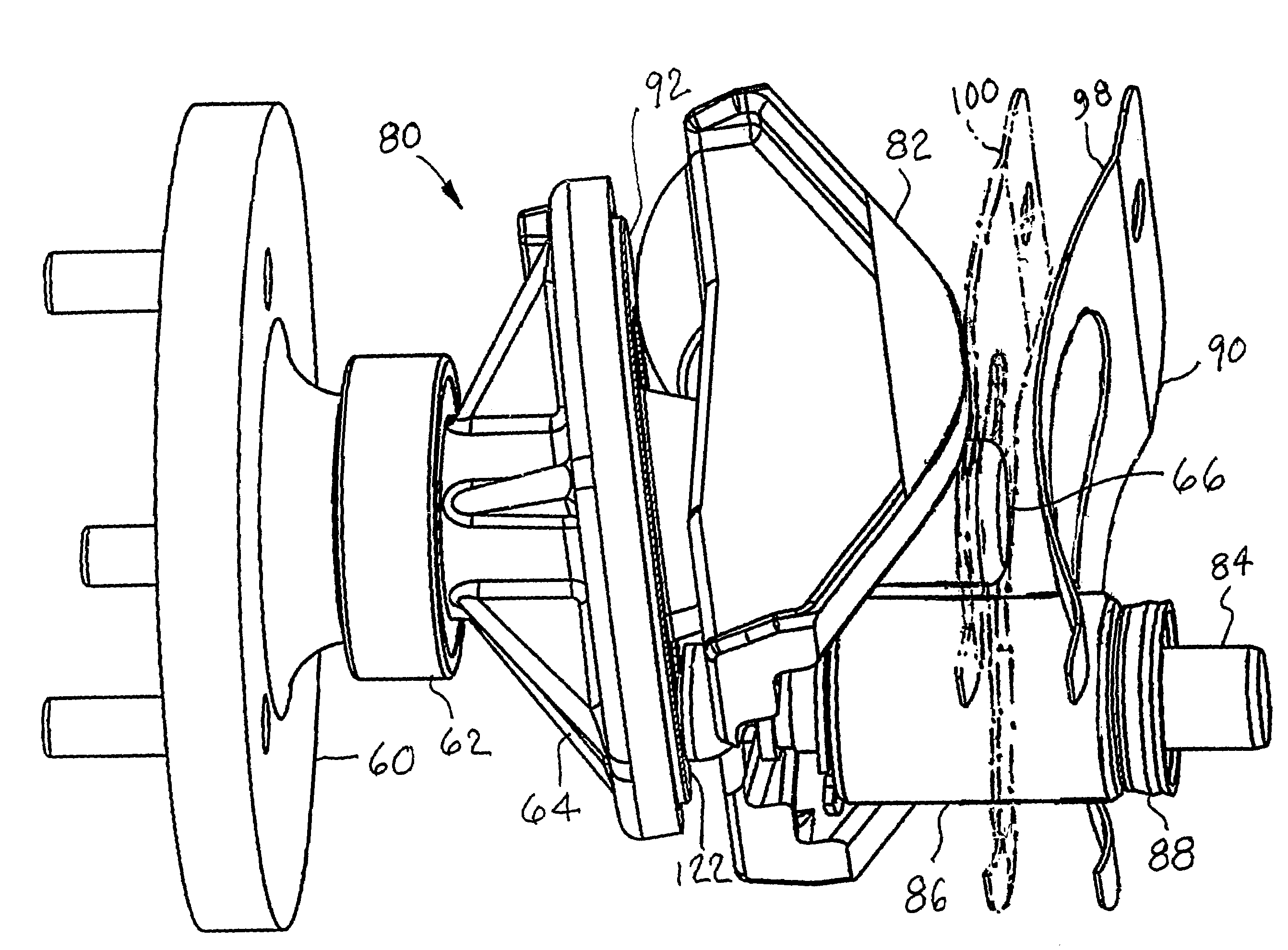
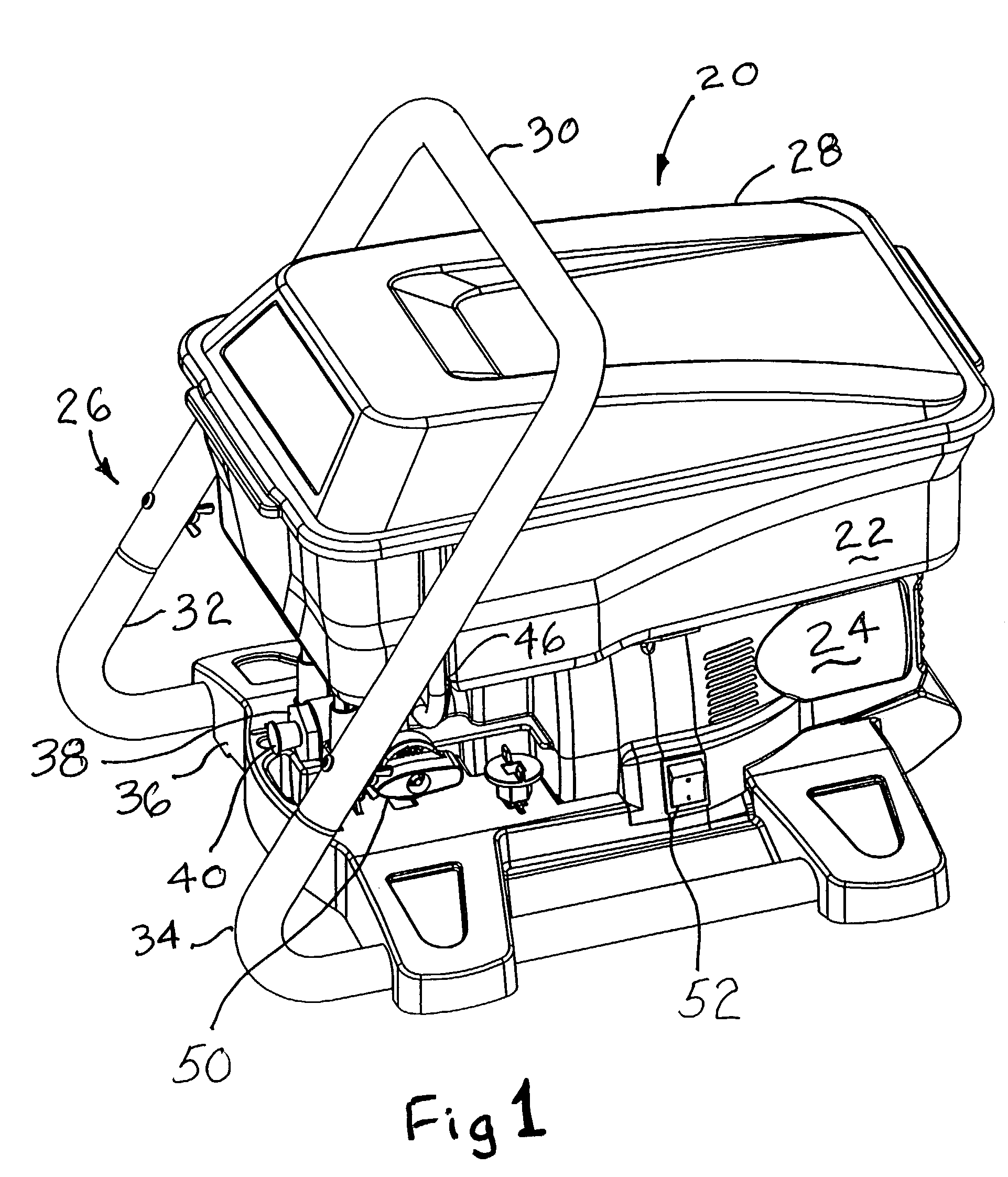
[0028]Referring to the Figures, and most particularly to FIGS. 1–4, a paint pump apparatus 20 useful in the practice of the present invention may be seen. Apparatus 20 is intended to pump paint and similar coatings at high pressure to a spray gun (not shown) for application to a surface to be coated via airless spraying. As will be described infra, the apparatus 20 utilizes a swashplate action to drive a piston in a reciprocating manner without relying on return springs or paint back pressure on the piston to maintain contact between the piston and swashplate on the return stroke.

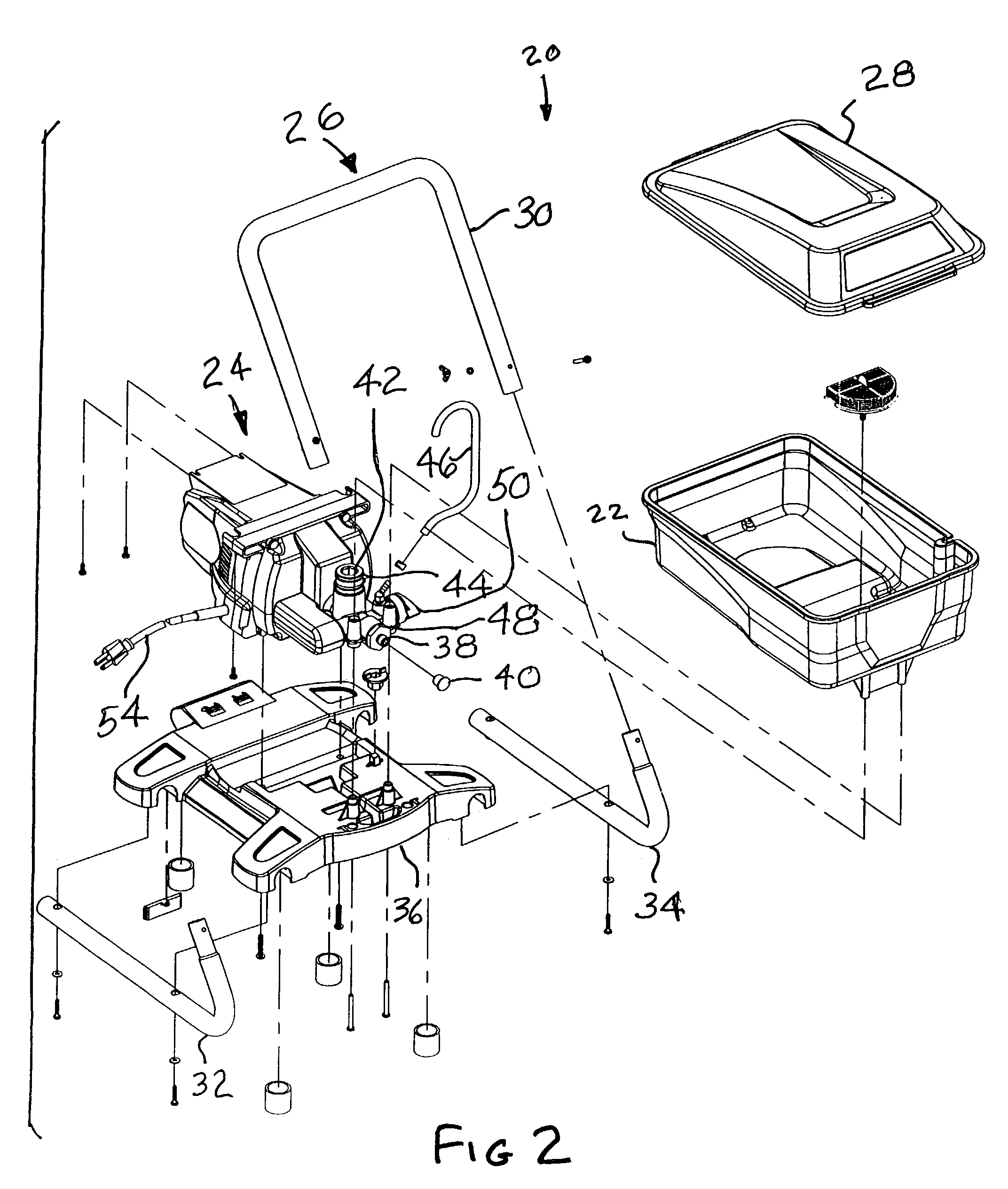
[0029]Apparatus 20 includes a paint reservoir 22 and a pump assembly 24 carried by a frame 26. Reservoir 22 may have a cover 28. Frame 26 preferably has a handle portion 30 and a pair of foot portions 32, 34. Foot portions 32 and 34 are received in a base 36 which supports pump assembly 24. It is to be understood that a high pressure hose (not shown) is connected to an outlet 38 of the pump assembly 24 afte...


PUM


Abstract

A piston pump assembly with a rotatingly driven swashplate in driving relationship with a rocker arm and piston engaged with one end of the rocker arm. A spring urges the rocker arm and piston into contact with an annular ring carried by a bearing in the swashplate. The spring may be a separate leaf spring or may be formed integrally with the rocker arm. The rocker arm engagement with the piston uses a spherical ball-joint-like surface. The contact between each of the rocker arm and piston and the annular ring utilize spherical surfaces on the rocker arm and piston, with an elongated footprint on the rocker arm and a circular footprint on the piston. The piston is allowed a slight radial play in operation.

Description

CROSS REFERENCE TO RELATED APPLICATIONS[0001]Reference is made to the following copending and commonly assigned United States Patent Applications by the same inventors, each of which was filed on the same day as the instant application, and each of which is hereby expressly incorporated by reference:[0002]i) STRAINER AND VALVE RELEASE, Ser. No. 10 / 427,446; and[0003]ii) FAN BAFFLE, Ser. No. 10 / 427,448.FIELD OF THE INVENTION[0004]This invention relates to the field of pumps for paint and related coating materials.BACKGROUND OF THE INVENTION[0005]In the past, various forms of pumps have been used to deliver paint (or other similar coating material) to a spray gun for atomization in airless spraying. Such pumps have included piston pumps, where the pistons have been driven using a variety of mechanisms, such as eccentric cams, scotch yokes, or cranks and connecting rods to convert rotary to linear motion. Each of these approaches have suffered from various drawbacks, both technical and ...

Claims


Application Information

Patent Timeline
IPC IPC(8): F04B37/00F01B3/00F04B1/12F04B1/29
CPCF04B1/126Y10T74/18384
Inventor COOPER, ROBERT D.CARPENTER, SCOTT R.
Owner WAGNER SPRAY TECH CORP
Why Eureka
Try Eureka