Self-cooling structure for cylinder of swashplate type plunger pump

A swash plate type plunger pump, self-cooling technology, applied in variable capacity pump components, components of pumping devices for elastic fluids, pumps, etc., can solve the aggravation of cylinder agitation, heat generation, rotation resistance, and internal leakage Increased cooling capacity and gaps cannot be effectively increased to achieve the effects of improving cooling efficiency and reliability, suppressing oil agitation and heating, and good oil flow direction

Inactive Publication Date: 2015-12-30
FUZHOU UNIV
View PDF11 Cites 15 Cited by
  • Summary
  • Abstract
  • Description
  • Claims
  • Application Information

AI Technical Summary

Problems solved by technology

This solution increases the leakage of the gap and reduces the efficiency of the pump. At the same time, the high-pressure leakage of the gap will also increase the heat of the pump.
In addition, at high speed, the plunger is subjected to a large centrifugal force and is close to the radially outer side of the cylinder body. In fact, the gap between the plunger and the radially outer side of the cylinder body cannot be effectively increased.
[0007] (2) Heat dissipation fins are added to the outer peripheral s

Method used


Image

  • Self-cooling structure for cylinder of swashplate type plunger pump
  • Self-cooling structure for cylinder of swashplate type plunger pump
  • Self-cooling structure for cylinder of swashplate type plunger pump

Examples


Embodiment Construction

[0038] In order to make the above-mentioned features and advantages of the present invention more comprehensible, the following specific embodiments are described in detail with reference to the accompanying drawings.

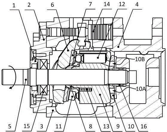
[0039] figure 1A schematic diagram schematically showing the internal structure of an embodiment of the present invention. The swash plate axial piston pump with cylinder self-cooling structure consists of end cover 1, pump cover 2, front pump body 3, middle pump body 4, transmission shaft 5, swash plate 6, bottom plate 7, spherical bushing 8, Cylinder 9, distribution plate 10, sliding shoe 11, plunger 12, cylinder spring 13, swash plate controller 14, ball bearing 15, needle roller bearing 16 and other parts. Wherein, the pump casing is composed of a pump cover 2, a front pump body 3, and a middle pump body 4. The transmission shaft 5 runs through the pump casing front and back, and is supported by ball bearings 15 and needle roller bearings 16 at the front ...


PUM


Abstract

The invention relates to a self-cooling structure for a cylinder of a swashplate type plunger pump. The self-cooling structure comprises the cylinder and a flow-distribution plate, wherein plunger cavities are formed in the front end surface of the cylinder, kidney-shaped holes communicated with the plunger cavities are formed in the back end surface of the cylinder, the back end surface of the cylinder is closely attached to the flow-distribution plate, axial cooling oil channels are formed in the cylinder, radial cooling oil channels for communicating the axial cooling oil channels with the outer circumferential surface of the cylinder are formed in the circumferential side of the cylinder, flow-distribution cooling oil channels for communicating the axial cooling oil channels with the back end surface of the cylinder are formed in the back end surface of the cylinder, an arc through hole-shaped low-pressure oil sucking area and high-pressure oil discharge areas are formed in two sides of a same end surface of the flow-distribution plate, oil grooves are formed between the low-pressure oil sucking area and the high-pressure oil discharge areas, and the plunger cavities are communicated with the low-pressure oil sucking area and the high-pressure oil discharge areas through the kidney-shaped holes. Under the action of the rotating centrifugal force of the cylinder and the pressure difference of the outer circumferential surface of the cylinder, the cooling efficiency is effectively improved; the specific oil grooves of the flow-distribution plate and the cooling oil channels of the cylinder are formed, and the cooling efficiency and reliability are further improved.

Description

technical field [0001] The invention relates to a cylinder self-cooling structure of a swash plate type plunger pump, in particular to a swash plate type plunger pump which can realize self cooling of the cylinder body under high-speed rotation. Background technique [0002] The swash plate plunger pump is widely used in aerospace, petrochemical, construction machinery and shipbuilding industries due to its advantages of compact structure, high power density ratio, high pressure and high efficiency, and flexible variable mode. At present, with the development of high-pressure axial piston pumps, the heat generated by the three main friction pairs (piston pair, flow distribution pair and sliding shoe pair) of the swash plate axial piston pump has further increased, and its working heat has accumulated It will increase the friction pair and cause damage such as sticking, which will greatly reduce the service life of the pump. [0003] For the plunger pair, the reciprocating m...

Claims


Application Information

Patent Timeline
IPC IPC(8): F04B53/08F04B53/16F04B53/18F04B1/22
Inventor 陈晖梁红星肖天丽王健
Owner FUZHOU UNIV
Why Eureka
Try Eureka