Movable machinery, including pavement working apparatus and methods of making

a technology of moving machinery and working apparatus, applied in the field of moving machinery, can solve the problems of heavy and difficult to maneuver machines, and achieve the effect of convenient use and sufficient strength

Inactive Publication Date: 2006-03-28
HUSQVARNA AB
View PDF32 Cites 16 Cited by
  • Summary
  • Abstract
  • Description
  • Claims
  • Application Information

AI Technical Summary

Benefits of technology

[0012]Methods and apparatus are described for producing a movable machine, for example a wall saw, having a light construction. Methods and apparatus are also described for producing a movable machine having light components and having strength sufficient to operate as a movable machine, for example in a wall saw. Methods and apparatus are discussed for producing components of a movable machine that can form a final assembly wherein at least one or part of one of the components is formed as a composite material, at least one component of which is plastic, for example a thermosetting resin. Methods and apparatus are also disclosed that can produce a movable machine that is more versatile and easier to use.
[0015]In another example of methods and apparatus disclosed herein, a movable machine, for example a saw, includes a housing formed from a cover material, for example a plastic skin, over a body layer, for example a foam layer. In one form, the foam layer is a high-density closed cell foam. In other forms, the body layer can be honeycomb material, a fiberglas composite, a metal or a plastic. The body layer can provide support to the plastic skin and impact resistance. In another form, the plastic skin can be formed from a composite material of reinforcing fibers and plastic, for example a thermosetting resin. In a further form, the skin and the body layer are bonded or adhered together with an adhesive.
[0016]In a further example of methods and apparatus disclosed herein, a movable machine, for example a saw, includes a carriage having a side wall for supporting carriage components, for example rollers or bearings, wherein the side wall has at least one surface that extends longitudinally as well as inward and outward relative to a longitudinal axis. For example, the longitudinal axis may coincide with a track along which the carriage travels and the surface of the side wall extends longitudinally as it extends inward and then outward relative to the track. The directional change in the surface may help to support diagonal loads in the carriage as well as loads tending to turn the carriage away from the track.
[0026]In an example of methods and apparatus disclosed herein, a movable machine, for example a wall saw, is formed with at least one component having a housing formed from at least one of, and preferably both, a composite and a foam with metal inserts bonded to one or both of the composite and the foam. Preferably, the inserts are formed from 6AL-4V titanium or from 2024-T351 aluminum that is hard anodized. These materials are lightweight, minimize galvanic action between the metal and carbon fiber and have high material yield properties. The gears may be formed from stainless steel, such as 416 stainless or 86L20 alloy, and the shafts may be stainless as well, but they may be lighter if formed from heat-treated aluminum or from titanium.

Problems solved by technology

Machine design sometimes results in machines that are difficult to maneuver and heavy.

Method used


Image

  • Movable machinery, including pavement working apparatus and methods of making
  • Movable machinery, including pavement working apparatus and methods of making
  • Movable machinery, including pavement working apparatus and methods of making

Examples


Embodiment Construction

[0086]The following specification taken in conjunction with the drawings sets forth examples of the present inventions in such a manner that any person skilled in the art can make and use the inventions. The examples of the inventions disclosed herein are the best modes contemplated by the inventor for carrying out the inventions in a commercial environment, although it should be understood that various modifications can be accomplished within the parameters of the present inventions.

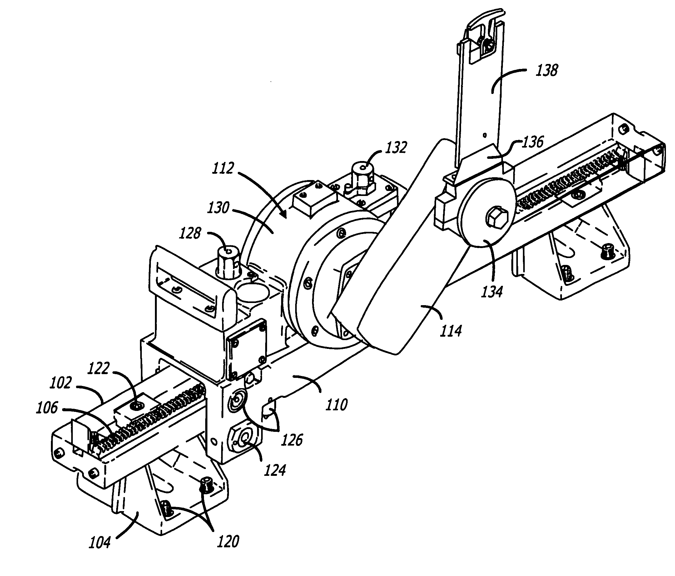
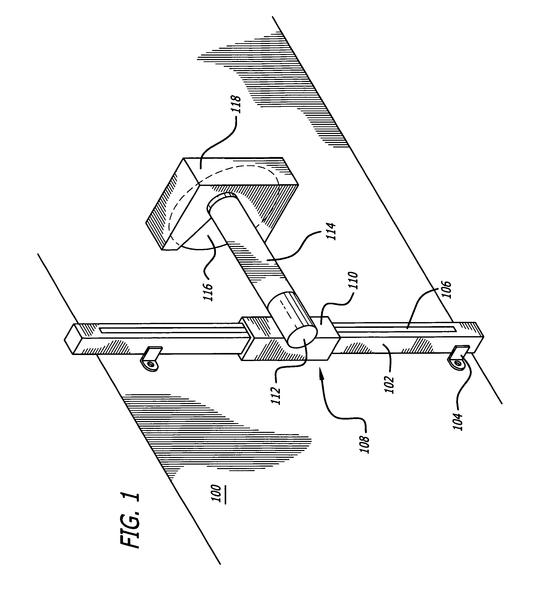
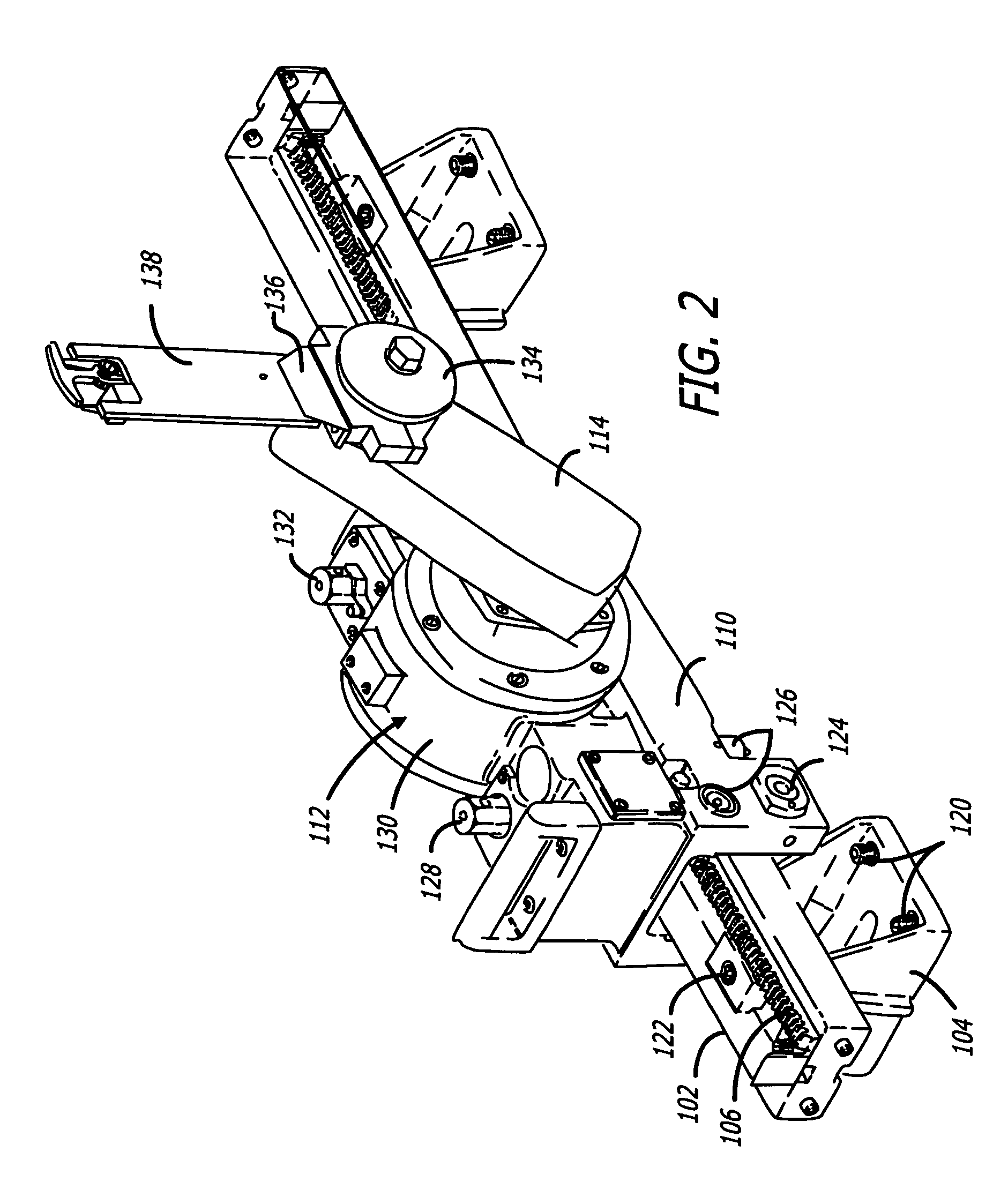
[0087]A movable or portable machine is described which is lighter than conventional counterparts, and which can be made more reliable. Methods and apparatus are also described for making an improved movable or portable machine, for example a movable machine for working on a work piece, in the disclosed example a wall saw. While the disclosed example is directed to a wall saw, the inventions can be applied to other movable machines, including hand-held machines and power tools, portable machines and powe...


PUM

PropertyMeasurementUnit
thicknessaaaaaaaaaa
adhesive thicknessaaaaaaaaaa

Abstract

A movable machine, for example a saw, has a light construction using composite materials such as fiber reinforced resins and a closed cell foam. The saw may have a housing formed from multiple skins of the composite materials in which is located the closed cell foam. Metallic inserts may be used to bond to either or both of the foam and the composite skin to accept working components. A saw is also described which uses gears sharing the same support element.

Description

CROSS-REFERENCE TO RELATED APPLICATION[0001]This is a continuation-in-part of Ser. No. 10 / 101,473, filed Mar. 18, 2002.BACKGROUND OF THE INVENTIONS[0002]1. Field of the Invention[0003]This relates to movable machinery, including hand-held, portable, self propelled and similar machinery, and including saws, drills for example coring drills, cutting and grinding machinery and other machinery for treating concrete, paving, masonry and the like.[0004]2. Related Art[0005]Machinery design for movable machinery takes into account the function of the machinery, strength and reliability, cost of materials and similar considerations. Machine design sometimes results in machines that are difficult to maneuver and heavy. Depending on the application, machinery such as saws are made primarily of metal parts and sometimes plastic housings, switches or controls to lower the weight of the product.[0006]While it should be understood that the present inventions may apply to a wide variety of differen...

Claims


Application Information

Patent Timeline
Patent Type & Authority Patents(United States)
IPC IPC(8): B24B23/00B23D47/00B23D45/04B23D47/12B23Q1/01B25F5/02B28D1/04
CPCB23D45/046B28D1/045B28D1/044B23D47/12B28D1/04B25F5/02
Inventor BARATTA, ANTHONY
Owner HUSQVARNA AB
Why Eureka
Try Eureka