Sprocket with wear limit indication

a technology of wear limit and sprocket, which is applied in the direction of gearing, gearing elements, hoisting equipment, etc., can solve the problems of sprocket tooth limit, sprocket meshing and chain no longer smooth, and sprocket tooth defects are generated, so as to avoid premature replacement of sprocket, maximize the use life of sprocket, and easy to recognize

Active Publication Date: 2006-03-28
TSUBAKIMOTO SPROCKET
View PDF4 Cites 15 Cited by
  • Summary
  • Abstract
  • Description
  • Claims
  • Application Information

AI Technical Summary

Benefits of technology

[0016]Because the wear indicating means are provided on a side, or on the sides, of a sprocket tooth, it is easy to determine visually whether or not the wear of the sprocket has reached its limit. Moreover, the location of the wear indicating means on the side of a tooth enables the condition of the sprocket to be determined even when the sprocket is installed in a machine. Since the wear determination means is located along the direction of the pressure angle, where the wear of the sprocket tooth proceeds most rapidly, the condition of the sprocket can be determined visually before the occurrence of fracture of the sprocket teeth, and the useful life of the sprocket can be maximized by avoiding premature replacement of the sprocket. When the wear determination means is provided on a sprocket tooth adjacent a keyway, the position of the wear determination means can be readily determined. The difference between the colors of the wear determination means and the base material of the sprocket, and that fact that the wear determination means is fitted into a groove or a hole on a side surface of a sprocket tooth, ensures that the wear limit marker will not disappear and can be easily recognized, even if the side of the sprocket is worn. Moreover, even if the sprocket is located behind other machine components, the determination of wear conditions can be carried out easily.

Problems solved by technology

There is a limit to the amount of wear that a sprocket tooth can sustain while still being able to mesh smoothly with a roller chain.
When the wear of the sprocket teeth exceeds this limit, the meshing of the sprocket and the chain is no longer smooth, and tooth defects are generated in the sprocket.
The use of a gauge for gap measurement, as shown in FIG. 7, is subject to several problems.
The sprocket is not always readily accessible.
If it is hidden behind other machine components, tooth form gauge measurement may not be possible.
The ink-rubbing transfer method is subject to errors due to shift and elongation of the paper.
Curvature of the tooth forms also prevents their shapes from being correctly transferred onto paper.
The use of a concave, wear-indicating groove is also subject to a number of problems.
Since the groove is positioned on each chain-contacting tooth surfaces, it reduces the available contact area, thereby increasing the contact surface pressure and increasing the rate at which wear of the sprocket teeth progresses.
Formation of the concave groove on the tooth surfaces is difficult and costly.
Finally, as in the case of the tooth form gauge, if the sprocket is hidden behind other machine components, the concave groove is difficult to see, and consequently the amount of wear is difficult to determine.

Method used


Image

  • Sprocket with wear limit indication
  • Sprocket with wear limit indication
  • Sprocket with wear limit indication

Examples


Embodiment Construction

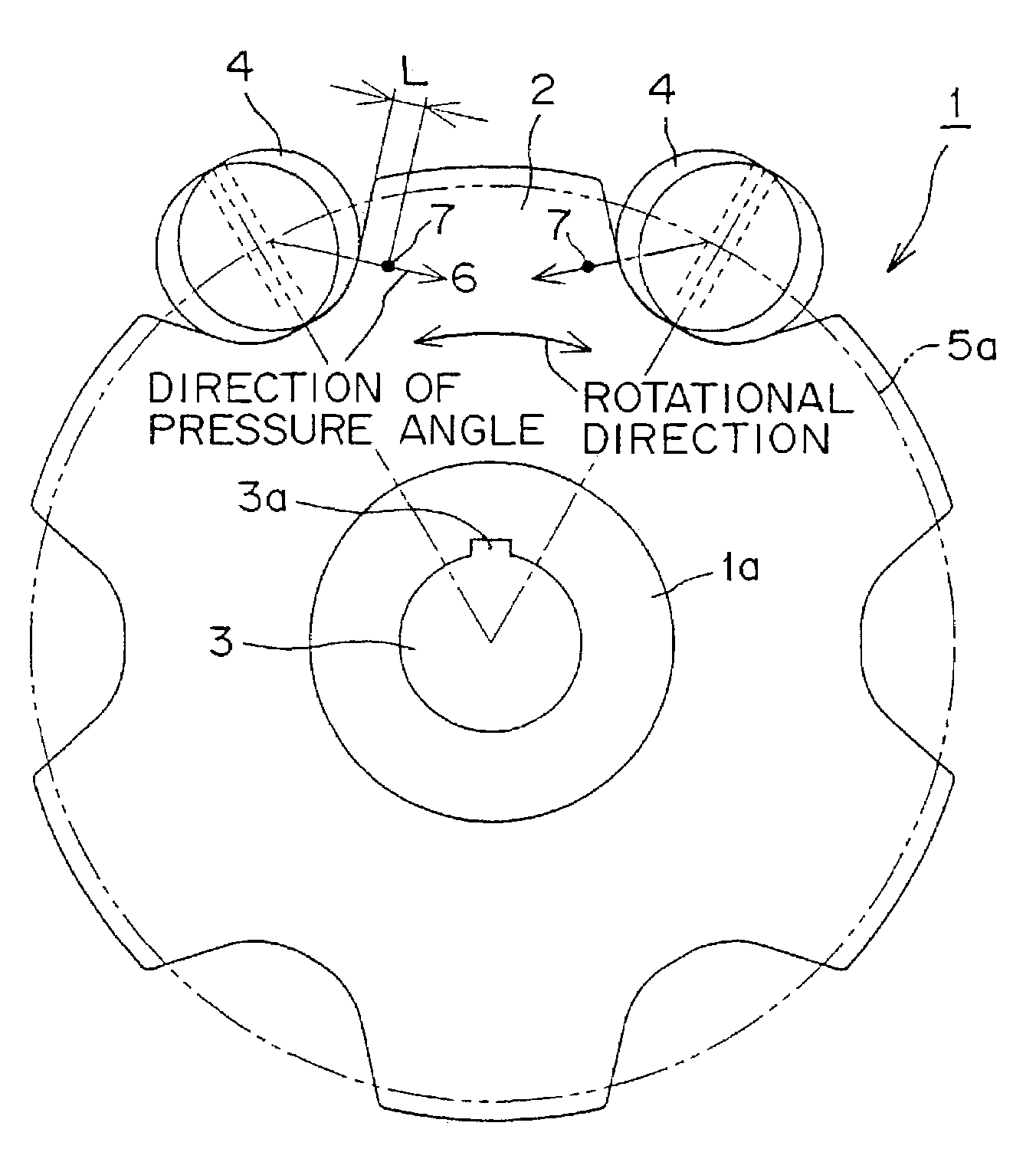
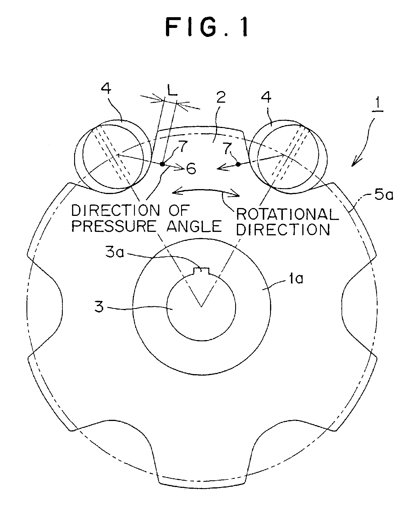
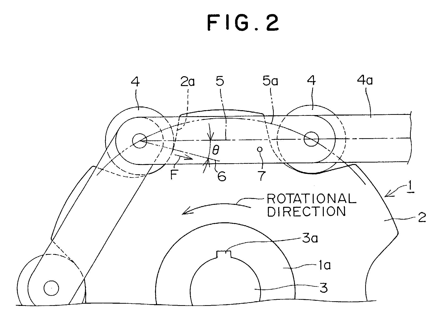
[0025]As shown in FIGS. 1 and 2, a sprocket 1 has teeth 2 on its outer circumference, and a central shaft hole 3 surrounded by a boss 1a. A keyway 3a is provided in the shaft hole 3. Rollers 4 in a roller chain are connected by plates 4a, shown in FIG. 2. A chain pitch line 5, shown in FIG. 2, extends from the center of a roller 4 to the center of a succeeding roller 4 in the chain. FIGS. 1 and 2 show a pitch circle 5a. θ denotes the pressure angle, and 6 denotes a direction of the pressure angle.

[0026]On a side surface of the tooth 2 positioned adjacent the keyway 3a, a wear limit marker 7, which serves as a wear determination means, is provided at a wear limit position in an area where the most wear occurs. The tooth on which the wear limit mark is located is preferably the tooth closest to the keyway, and preferably a tooth intersected by an imaginary radial line (not shown) extending from the axis of rotation of the sprocket through the keyway. The wear limit marker 7 is provide...


PUM


Abstract

In a sprocket for use with a roller chain, a wear limit marker, having a different color from that of the base material of the sprocket, is provided on side surface of a sprocket tooth adjacent to a keyway. The wear limit marker is disposed on an imaginary line extending in the direction of the pressure angle, and is located in a hole or groove provided in a side surface of the sprocket tooth. The marker makes it possible to determine easily and reliably whether or not wear at the location at which wear of a sprocket tooth proceeds most rapidly is within a predetermined limit, and the location of the marker makes it possible to evaluate wear conditions even when the sprocket is installed in a machine.

Description

FIELD OF THE INVENTION[0001]This invention relates to a sprocket for use with a roller chain, a bushing chain, or the like, and particularly to a sprocket having a wear limit indicator.BACKGROUND OF THE INVENTION[0002]In a chain drive, when a roller chain is in mesh with a sprocket to transmit power, wear is produced on the tooth surfaces of the sprocket, particularly as a result of sliding contact at the location where the sprocket meshes with the chain, as described in detail below.[0003]Referring to FIG. 5 of the drawings, when a sprocket tooth 11 and chain roller 12 mesh with each other, contact usually occurs at a fixed contact position 13. At the contact position, a force F is applied by the roller 12 to the sprocket tooth surface 11a in a fixed direction. The force F acts along a direction 14, which corresponding to the pressure angle θ determined by the shape of the sprocket teeth.[0004]The force F results in increased contact surface pressure at the contact position, and ge...

Claims


Application Information

Patent Timeline
Patent Type & Authority Patents(United States)
IPC IPC(8): F16H55/30
CPCF16H55/30F16H2057/012
Inventor NAKAMURA, KENICHIRO
Owner TSUBAKIMOTO SPROCKET
Why Eureka
Try Eureka