Unlock instant, AI-driven research and patent intelligence for your innovation.

Engine starter with impact absorber

a technology of impact absorber and engine, which is applied in the direction of electric generator control, slip coupling, gearing, etc., can solve the problems of reducing the production cost of the engine starter, and achieve the effect of ensuring the stability of sliding motion of the friction plate, reducing the length and simplifying the structure of the impact absorber

Inactive Publication Date: 2006-03-28
DENSO CORP
View PDF13 Cites 22 Cited by
  • Summary
  • Abstract
  • Description
  • Claims
  • Application Information

AI Technical Summary

Benefits of technology

The invention is an engine starter with an impact absorber that prevents damage to the starter from excessive impact torque. The impact absorber includes a friction plate between the carrier plate and clutch outer, which can absorb the impact energy and reduce the size of the starter. The use of the friction plate eliminates the need for additional parts and increases the service life of the impact absorber. The overrunning clutch also includes an elastic member to absorb the impact energy and allow for a decreased size of the starter. The impact absorber can be designed to be reduced in size and cost of production.

Problems solved by technology

This results in a decrease in production costs of the engine starter.

Method used


Image

  • Engine starter with impact absorber
  • Engine starter with impact absorber
  • Engine starter with impact absorber

Examples


first embodiment

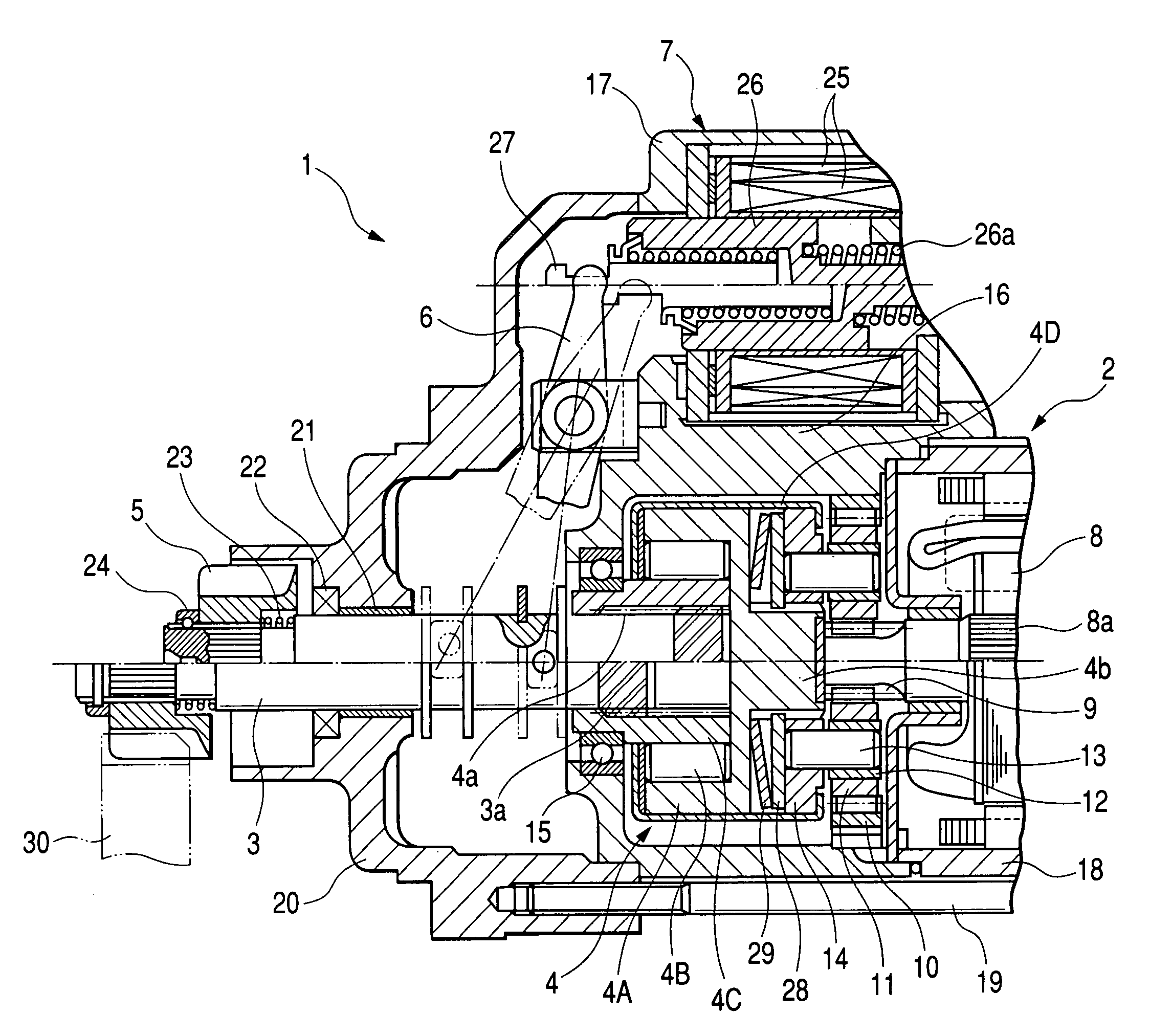
[0023]Referring to the drawings, wherein like reference numbers refer to like parts in several views, particularly to FIG. 1, there is shown a starter 1 according to the invention which will be discussed below as an engine starter to be mounted in an automotive vehicle to start an internal combustion engine thereof. The starter 1 consists essentially of an electric motor 2, a planetary gear train, as will be described later in detail, an overrunning clutch 4 (also called a one-way clutch), a pinion gear 5, a solenoid switch 7, and an impact absorber, as will be described later in detail. The planetary gear train works to lower an output speed of the motor 2 and transmit it to an output shaft 3 through the overrunning clutch 4. The solenoid switch 7 works to selectively cut or supply an electric current to energize the motor 2 and also move the output shaft 3 in an axial direction (i.e., a lateral direction as viewed in the drawing) of the starter 1 through a shift lever 6. The impac...

second embodiment

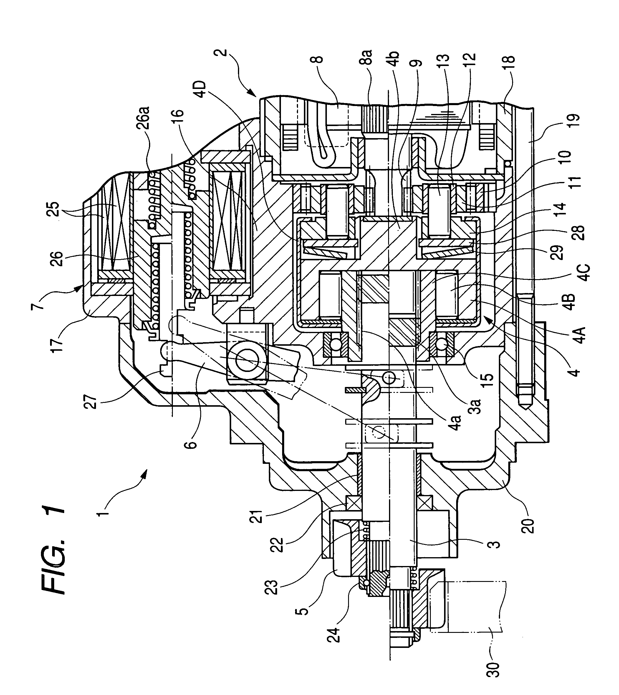
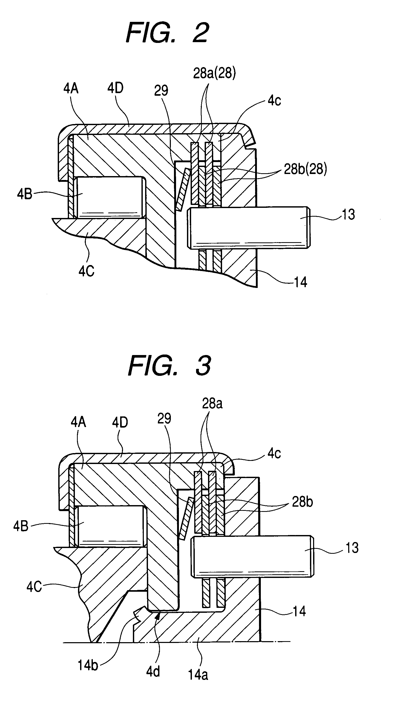
[0050]FIG. 2 shows an impact absorber according to the invention.

[0051]The impact absorber includes a frictional assembly 28 made up of first friction plates 28a and second friction plates 28b. The first friction plates 28b are fitted within a cylindrical extension 4c formed integrally with the clutch outer 4A. The second friction plates 28b engage the gear spindles 13 each of which is press fit in the carrier plate 14. The first friction plates 28a and the second friction plates 28b are arrayed alternately in frictional abutment with each other.

[0052]The structure of this embodiment uses the gear spindles 13 to preclude relative rotation between the second friction plates 28b and the carrier plate 14. Specifically, the second friction plates 28b have formed therein circular holes into which the gear spindles 13 are fitted, thereby causing the second friction plates 28b to be rotated by the gear spindles 13. This eliminates the need for forming protrusions or grooves in the carrier ...


PUM


Abstract

An engine starter equipped with an impact absorber. The impact absorber is arranged between a planetary gear train and an overrunning clutch of the starter. The absorber includes a friction plate which is disposed between a clutch outer and a carrier plate of the overrunning clutch and urged elastically into frictional abutment with the carrier plate. This structure eliminates the need for installing the friction plate on an internal gear of the planetary gear train, thus permitting the internal gear to be reduced in size.

Description

BACKGROUND OF THE INVENTION[0001]1. Technical Field of the Invention[0002]The present invention relates generally to an electrical starter which may be employed to start automotive engines, and more particularly to such a starter equipped with an impact absorber disposed between a planetary gear train and an overrunning clutch to absorb undesirable impact energy.[0003]2. Background Art[0004]Japanese Patent First Publication No. 63-277859 discloses an engine starter for automotive vehicles which is equipped with a impact absorber. FIG. 4 shows such an engine starter. The impact absorber installed in the engine starter is made up of a center casing 100, a stationary disc 110 secured fixedly to the center casing 100, and a rotary disc 120 interposed between the center casing 100 and the stationary disc 110 in frictional contact therewith. The rotary disc 120 is fitted at an end thereof within a groove 131 formed in an internal gear 130 to be rotatable together with the internal gear 13...

Claims


Application Information

Patent Timeline
Patent Type & Authority Patents(United States)
IPC IPC(8): F16H3/72F02N11/00F02N15/02F02N15/06F16D7/02F16D43/21F16H1/28F16H35/10H02K7/116
CPCF02N15/063F02N15/067Y10T74/13Y10T74/134Y10T74/137F16H1/28
Inventor HASEGAWA, YOUICHIKAJINO, SADAYOSHI
Owner DENSO CORP