Magnetic controlled loading device in combination of a power generating set and an adjusting drive mechanism

Inactive Publication Date: 2006-03-28
LIN LILY
View PDF11 Cites 76 Cited by
  • Summary
  • Abstract
  • Description
  • Claims
  • Application Information

AI Technical Summary

Benefits of technology

[0009]The main object of the invention is to provide an eddy current magnetic controlled loading device by fully utilizing limited space without increasing the volume of the flywheel and internal components. A rotor and a stator are carefully set in the center of the magnetically controlled loading device, which makes the rotor's permanent magnet to be set on

Problems solved by technology

Although eddy current magnetic controlled loading devices have their advantages and features, yet if the loading portion uses permanent magnets as its magnetic field source, then it is very difficult to link up to external digital signals, and thereby unable to attain the goal of computerization and digitization, unless there is a motor and motor controller to change the relative location of the magnets and conductors, or utilizing magnetic wire coils and external power sources to overcome these problems.
However, in many situations, using external power sources creates a lot of inconvenience and thus greatly reduces its pract

Method used


Image

  • Magnetic controlled loading device in combination of a power generating set and an adjusting drive mechanism
  • Magnetic controlled loading device in combination of a power generating set and an adjusting drive mechanism
  • Magnetic controlled loading device in combination of a power generating set and an adjusting drive mechanism

Examples


Embodiment Construction

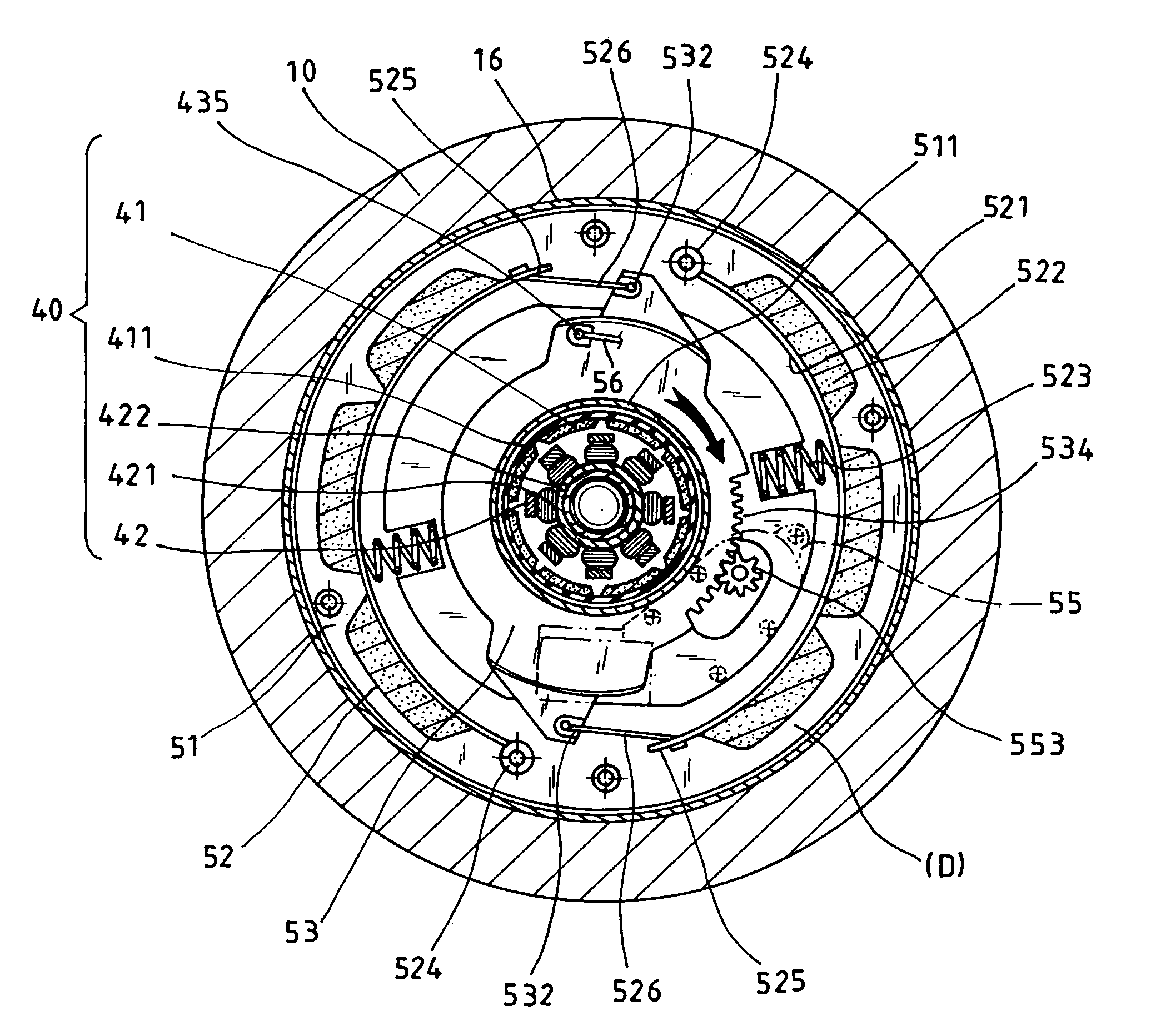
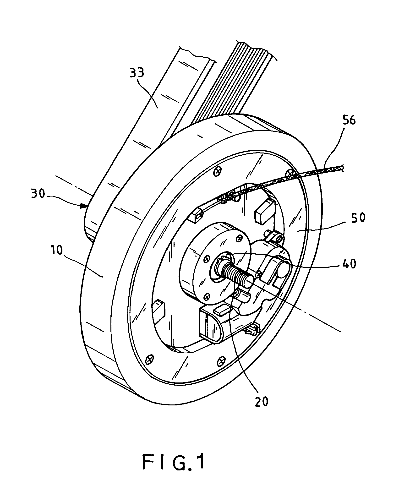
[0020]First, please refer to FIG. 1. The invention mainly includes: a flywheel 10, a shaft 20, a transmission element 30, a belt 33 that turns the transmission element 30, a micro power generating set 40 placed in the center of the flywheel 10, and a magnetic controlled loading device 50 placed on the flywheel's receptacle.

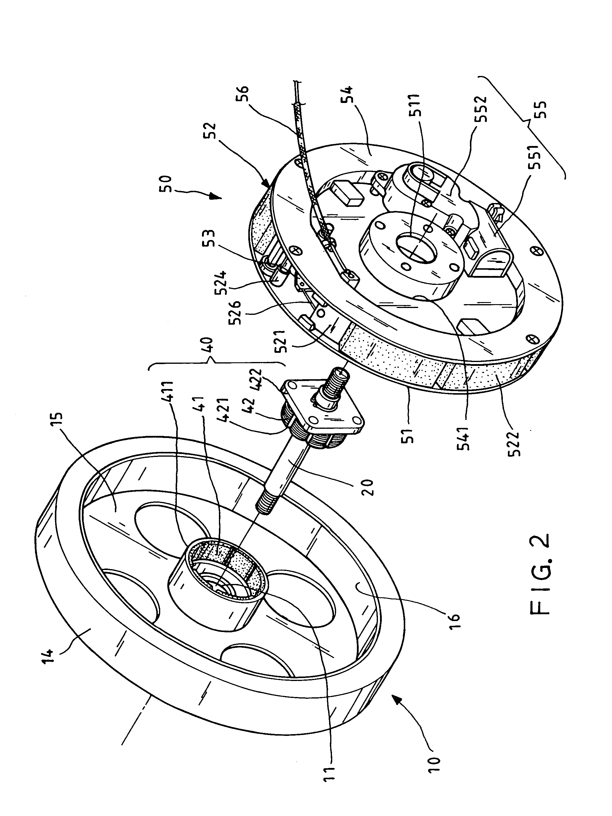
[0021]Please refer to the exploded diagram in FIG. 2 along with the cutaway view in FIG. 5. A first and a second bearing 12, 13 is disposed within a hub 11 of the flywheel 10, is (see FIG. 5). The flywheel 10 is recessed under a wheel rim 14, which forms a receptacle 15. A metal conductor 16 is mounted on the inner surface of the wheel rim 14. As shown in FIG. 5, the transmission element 30 is positioned on an outer end of the flywheel 10 and used to turn the flywheel 10. The transmission element 30 can be directly coupled with the flywheel 10. Alternatively, a third bearing 31 is interposed between the transmission element 30 and the shaft 20 while a single direc...


PUM


Abstract

A magnetic controlled loading device in combination of a power generating set and an adjusting drive mechanism having a flywheel, a shaft, a transmission element, a magnetic controlled loading device, a micro power generating set and an adjusting drive mechanism integrated into one single unit. It can also be taken apart and used in various combinations. By fully utilizing the limited space without increasing the volume of the flywheel and internal components, a rotor and a stator are disposed in the center of the magnetic controlled loading device. This makes the rotor's permanent magnets to be set on top of the flywheel's inner ring, so that when the flywheel is in operation, it turns into a micro power generating set. By utilizing its self generating power supply, it can provide the power needed by a small motor and by manual adjustments it can also control the changes in magnetic flux density between the flywheel and device as well to achieve continuous adjustment of loading resistance.

Description

BACKGROUND OF THE INVENTION[0001]1. Field of the Invention[0002]The invention relates to a loading device installed in exercise or rehabilitation equipment used to control motion resistance, and more particularly to a loading device that combines a magnetic controlled loading device, a micro electric generator and an adjusting drive structure into a single system, which can also be taken apart and used in various combinations. The change in the magnetic flux density of the loading device can be adjusted electrically or manually in order to achieve continuous adjustment of loading resistance.[0003]2. Description of the Related Art[0004]U.S. Pat. No. 5,711,404, the “magnetic adjustable loading device with eddy current,” refers to the eddy current resistance formed by using changes in the magnetic field, thus becoming a braking loading method. As it is a non-contact magnetic control and easy to link up with a personal computer, therefore, it is widely accepted by the market. Its fundam...

Claims


Application Information

Patent Timeline
IPC IPC(8): A63B22/06B60L7/00H02K7/02
CPCA63B21/0052A63B21/0053H02K49/043H02K7/20A63B21/225H02K2213/09
Inventor LIN, LILY
Owner LIN LILY
Why Eureka
Try Eureka