Device for applying a coating agent

a coating agent and device technology, applied in the direction of spray nozzles, liquid spraying apparatuses, special dispensing means, etc., can solve the problems of generating constant coating thickness, reducing the application efficiency of coating agents, so as to achieve precise sensor arrangement, increase the outflow rate, and high degree of precision

Inactive Publication Date: 2006-03-28
AMTEC KISTLER
View PDF6 Cites 3 Cited by
  • Summary
  • Abstract
  • Description
  • Claims
  • Application Information

AI Technical Summary

Benefits of technology

[0009]Advantageous embodiments and functional improvements of the independent measures are given in the dependent claims. Thus, the position of the substrate within its path passing the spray nozzle can be functionally detected via a path measurement device, whose output is at the input of a target value control element constructed as a computer in which the desired coating thickness and / or the desired coating thickness profile is saved and which forms the target value for the outflow rate from the instantaneous value of the position of the substrate and the coating thickness allocated to this position. These measures produce a multistage adjustment in which in an advantageous manner via the path measurement, the speed of the substrate is also observed so that a high degree of precision is also achieved for a desired coating thickness profile.
[0010]An additional advantageous measure can consist in that the regulator has an additional target value input for the desired temperature of the coating medium and an additional actual value input for the temperature in a supply section arranged before the nozzle opening and from the deviation, forms a control signal for adjusting a heating device allocated to a supply section arranged before the nozzle opening. These measures make it possible in an advantageous way not only to keep a constant temperature, but moreover, they also allow a change of the temperature in addition to the change of the nozzle opening and thus they produce an additional possibility for influencing the outflow rate. This can be advantageous especially if for an adjusted, largest opening, an additional increase in the outflow rate is necessary.
[0011]Advantageously, the supply line feeding the spray valve with coating medium can be provided with a Venturi-type diaphragm which has a pressure regulator allocated to it. These measures produce a simple and thus a very precise sensor arrangement to analyze the mass flow in the supply line.
[0012]In an additional embodiment of the independent measures, a display and / or recording device can be provided to display and / or record the deviation. This measure enables a simple control and makes easier a subsequent error search.
[0013]Functionally, the regulator can be integrated into the allocated spray valve. This produces a simple and compact embodiment in which a peripheral wiring is rendered unnecessary.
[0014]An additional advantageous embodiment of the independent measures can consist in that over the width of the substrate, several spray valves are provided, each controllable by a regulator, and that the regulators of all spray valves are connected to a common target value control element in which the coating thickness profiles of the zones of the substrate that are allocated to the spray valves are saved. The common target value control element also forms the target values for all spray valves, whereby between the target value control element and the regulators of the spray valves, a data bus can be advantageously provided. In this way, an especially simple and compact design can be achieved.

Problems solved by technology

However, disturbance variables such as a contaminant present in the area of the nozzle opening, a change of the viscosity of the coating medium and the like, can lead to inaccuracies.
As a result, a lack of lubricant can occur which leads to a damage of the deep draw formed body during the deep draw operation, and thus to the production of rejects.
An additional disadvantage can be observed in that even during orderly functioning, only the constant coating thickness can be generated.
It must, however, be oriented to the maximum requirement that is present at only a few points, thus resulting in an unnecessarily high consumption of coating medium.

Method used


Image

  • Device for applying a coating agent
  • Device for applying a coating agent
  • Device for applying a coating agent

Examples


Embodiment Construction

[0019]The main area of application of the invention presented here is the deep-draw deformation of sheet metals. During deep-drawing, sliding movements occur between tool and workpiece. In order to allow for a clean, disturbance-free sliding, the sheet metals fed to the deep-drawing press are coated with a lubricant, usually oil. This coating is usually done on both sides. Since the sheet metals, however, are not exposed to a sliding movement over their entire surface, a distribution of the lubricant according to the requirements on the surface of the sheet metal to be deformed is desired in order to save lubricant.

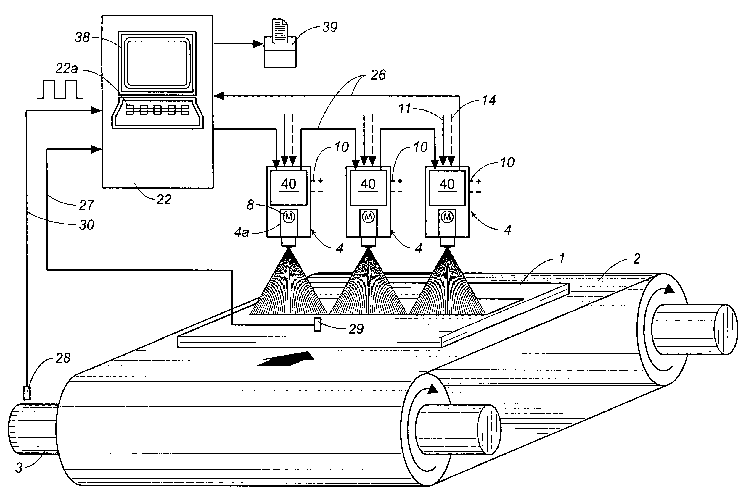
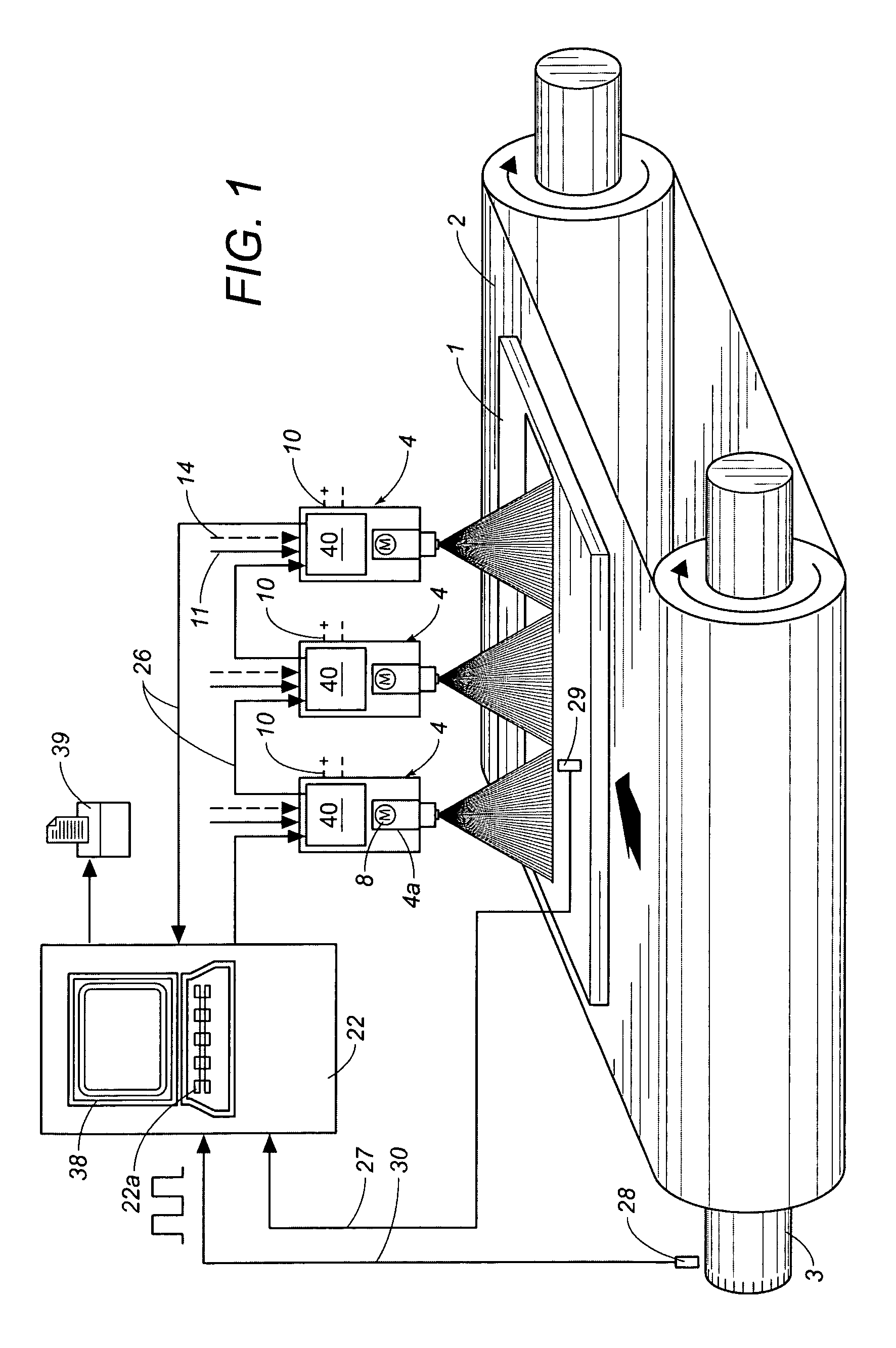
[0020]The material to be deformed using the deep-drawing press, i.e. the substrate, is fed to the deep-drawing press either in the form of sheet metal plates or in the form of a continuous band. The arrangement according to FIG. 1 is based on the processing of sheet metal plates 1. They follow each other at uniform distances on a conveyor device 2 (not shown in greater de...


PUM


Abstract

A device for applying a coating medium onto a substrate, includes at least one spray valve that has a nozzle opening that can be adjusted with regard to its effective outlet area using a closing mechanism, whereby the substrate can be moved past the spray valve, which can be supplied with the coating medium under pressure via a supply line, whereby the positioning device is assigned a regulator that has at least one target value input for the instantaneously required outflow rate of the coating medium from the spray valve and at least one actual value input for the mass flow rate through a supply section arranged in front of the nozzle opening, and from the deviation between these values, the regulator forms an adjustment signal that moves the positioning device in the direction to offset the deviation.

Description

RELATED U.S. APPLICATIONS[0001]Not applicable.STATEMENT REGARDING FEDERALLY SPONSORED RESEARCH OR DEVELOPMENT[0002]Not applicable.REFERENCE TO MICROFICHE APPENDIX[0003]Not applicable.FIELD OF THE INVENTION[0004]The invention involves a device for applying a coating medium onto a substrate, in particular for the application of a lubricant onto a sheet metal that can be fed into a deep drawing press, whereby the device has at least one spray valve that has a nozzle opening that can be adjusted with regard to its effective outlet area using a closing mechanism that can be positioned by an allocated positioning device. The substrate can be moved past the spray valve, which can be supplied with the coating medium under pressure via a supply line.BACKGROUND OF THE INVENTION[0005]An arrangement of this type is given in the German patent DE 101 39 633.3. The arrangement described in this document functions for the purpose of generating a constant coating thickness of the lubricant onto the ...

Claims


Application Information

Patent Timeline
Patent Type & Authority Patents(United States)
IPC IPC(8): B05C11/10B05B7/06B05B12/08B05B12/10
CPCB05B12/10B05B1/3053B05B7/066B05B7/1693B05B12/085B05B12/122
Inventor KISTLER, LEONHARDVOGEL, ROBERT
Owner AMTEC KISTLER
Why Eureka
Try Eureka