Integrated modem and line-isolation circuitry with HDLC framing and associated method

Inactive Publication Date: 2006-03-28
SILICON LAB INC
View PDF34 Cites 10 Cited by
  • Summary
  • Abstract
  • Description
  • Claims
  • Application Information

AI Technical Summary

Benefits of technology

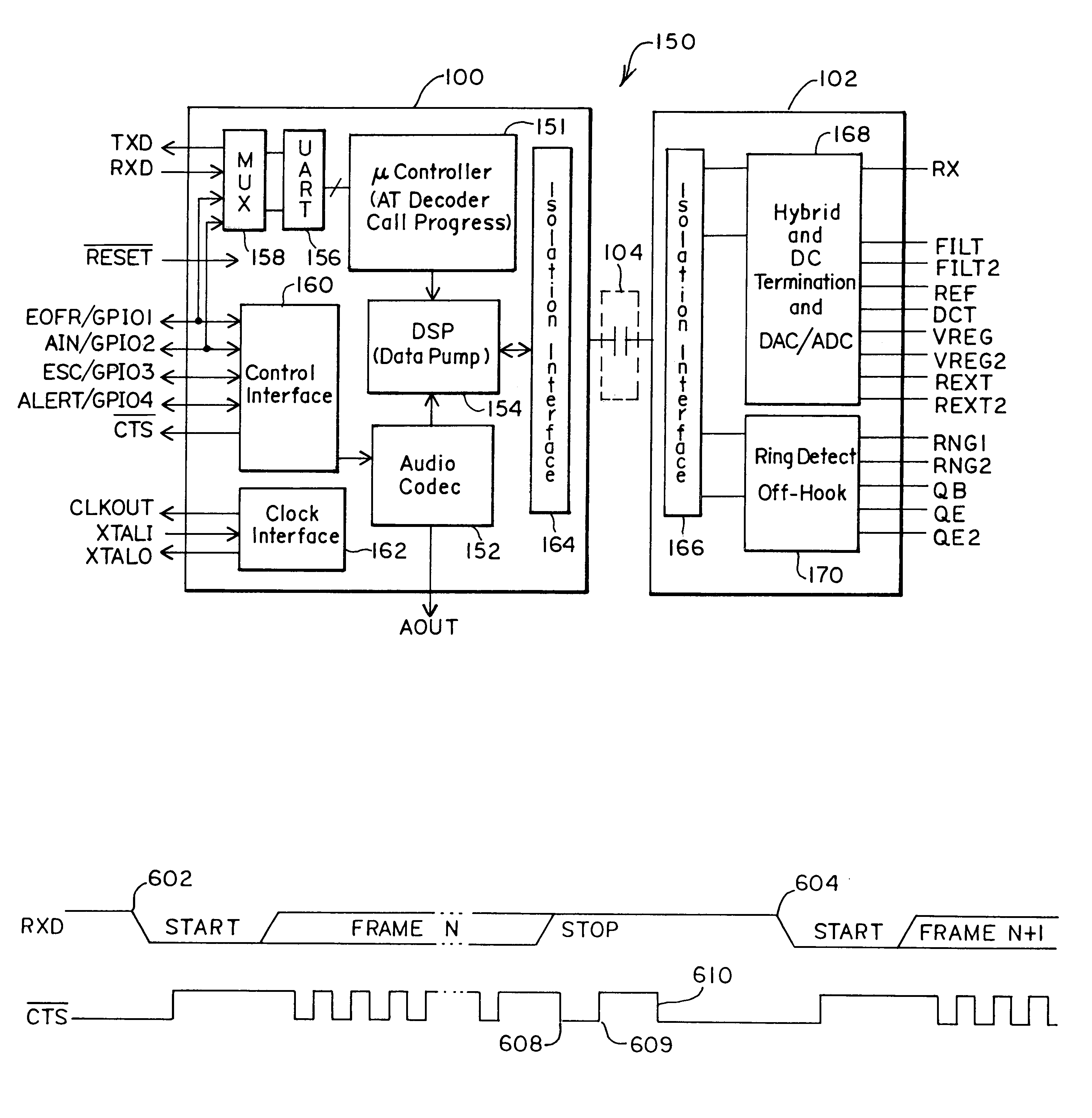
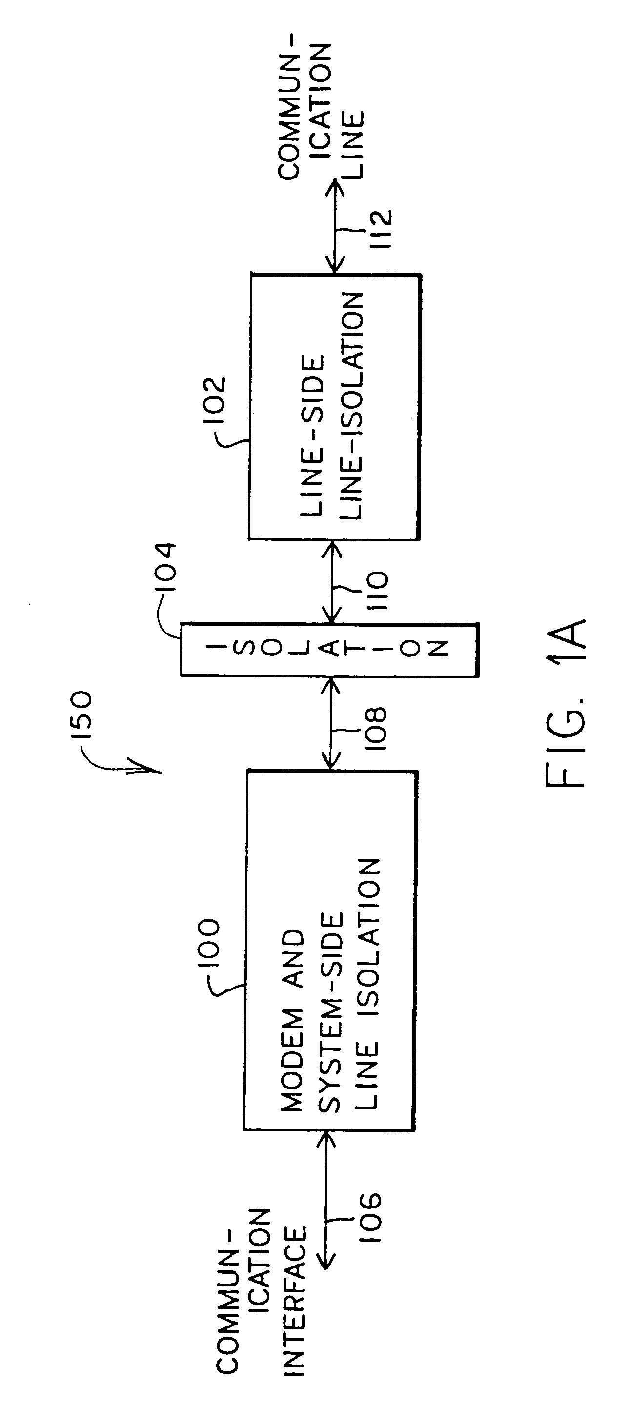
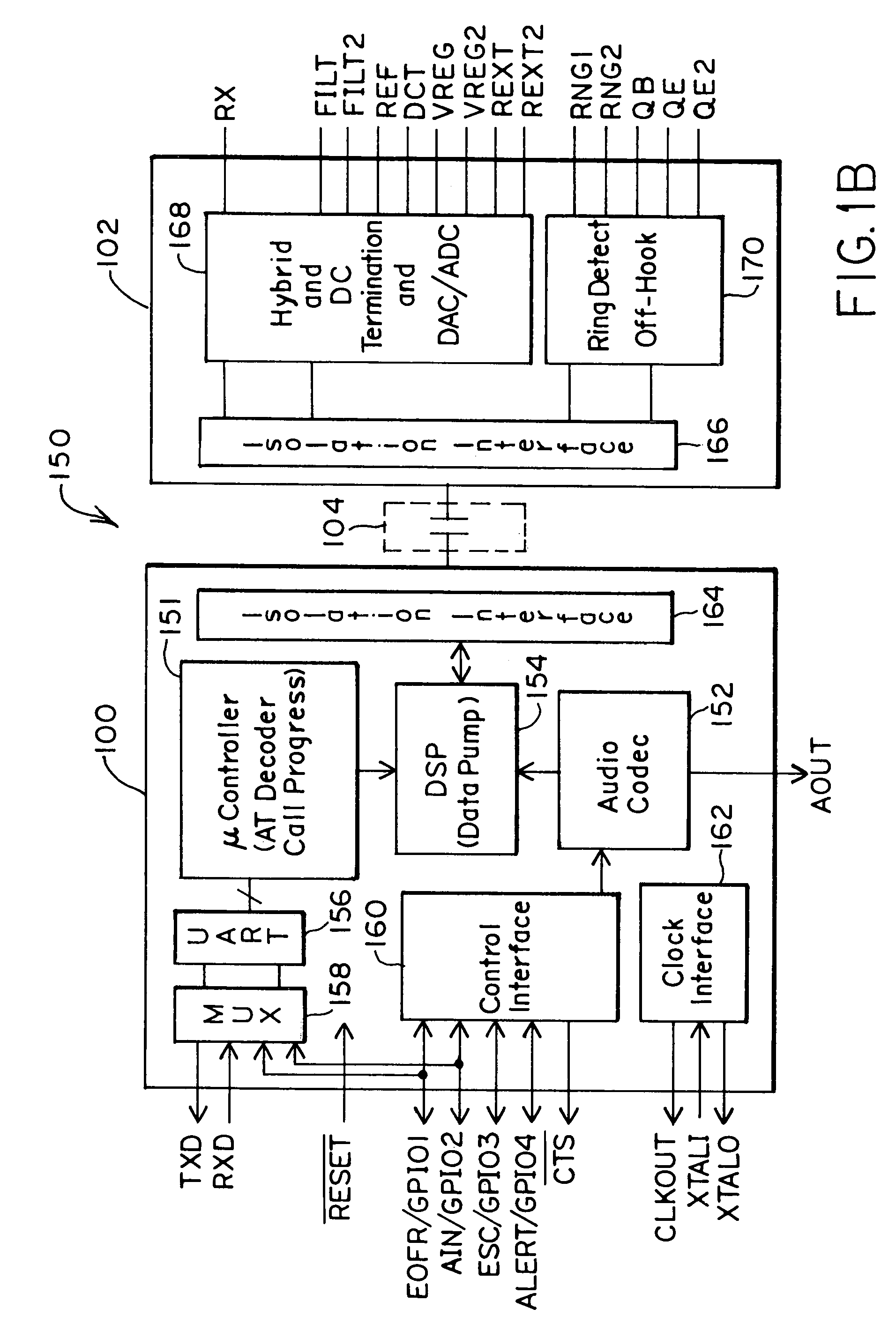
[0005]The present invention provides an improved modem architecture and associated method that integrate modem and line-isolation circuitry so as to achieve modem functionality and system-side isolation functionality on a single integrated circuit while also providing a modem interface that allows synchronous modem transmission protocols to be implemented through an asynchronous serial interface. For example, one such type of synchronous modem transmissi

Problems solved by technology

Although typical microprocessor and digital-signal-processor (DSP)-based multimedia chips employed in set-top boxes and other systems are capable of implementing a low-speed modem, they would do so at an undesirable manufacturing complexity and expense.
Such modem architectures suffer from numerous disadvantages.

Method used


Image

  • Integrated modem and line-isolation circuitry with HDLC framing and associated method
  • Integrated modem and line-isolation circuitry with HDLC framing and associated method
  • Integrated modem and line-isolation circuitry with HDLC framing and associated method

Examples


embodiment 350

[0042]FIG. 3B is a block diagram of an embodiment 350 in which data mode operations are desired. The output 316A and the input 316B of the DSP circuitry 154 are connected to the isolation interface 164 and are also combined to provide an input 320B to the DAC 310. The analog out AOUT 214, therefore, is a combination of the DSP input signal 316B and the DSP output signal 316A. This mixed sum may be used for call progress monitoring through an external speaker. In addition, the relative levels of the DSP input and output signals 316A and 316B may be programmed through the interface 106.

embodiment 352

[0043]FIG. 3C is a block diagram of an embodiment 352 in which voice mode operations are desired. The input 316B to the DSP circuitry 154 is connected to the isolation interface 164. The output 316A of the DSP circuitry 154 is combined with the DSP input 316B to provide an input 320B to the DAC 310. The Analog out AOUT 214, therefore, is a combination of the DSP input signal 316B and the DSP output signal 316A. The ADC 312 takes the analog in AIN 216 and provides a digital signal 320A for the isolation interface input 316C. In this configuration for path control circuitry 306, the analog out AOUT 214 provides a voice output, and the analog in AIN 216 provides a voice input. In addition, the DSP circuitry 154 may process these signals, if the modem processor 404 of FIG. 4 is not being bypassed for PCM data mode.

[0044]For this voice mode of operation embodiment of FIG. 3C, voice information may be received through the analog in AIN connection 216, processed by the ADC 310 and sent acr...

embodiment 354

[0045]FIG. 3D is a block diagram of an embodiment 354 in which test mode operations are desired. In this configuration for the path control circuitry 306, the DSP output signal 316A and the DSP input signal 316B are connected together. These connections allow for the DSP circuitry to be more easily tested through the external interface 106. Similarly, the output 320A of the ADC 312 and the input 320B of the DAC 310 are connected together. These connections allow for the voice CODEC 152 to be more easily tested.


PUM


Abstract

An improved modem architecture and associated method that integrates modem and line-isolation circuitry so as to achieve modem functionality and system-side isolation functionality on a single integrated circuit while also providing a modem interface that allows synchronous modem transmission protocols to be implemented through an asynchronous serial interface is disclosed. For example, one such type of synchronous modem transmission protocol is the HDLC (high-level data link control) protocol. According to the techniques disclosed herein, data and control information of an HDLC protocol may be presented at transmit and receive pins of a modem / system side DAA through an UART even though the UART may be an asynchronous serial receiver transmitter. Thus, both transmit and receive data transfers of a serial modem protocol may be implemented through an asynchronous serial interface.

Description

[0001]This application claims priority from Provisional Application Ser. No. 60 / 145,475 to Timothy J. Dupuis, Andrew W. Krone and Mitchell Reid, which was filed Jul. 23, 1999, and is entitled “POWERED SIDE DAA CIRCUIT HAVING MODEM CIRCUITRY.”TECHNICAL FIELD OF THE INVENTION[0002]This invention relates to modem architecture for communication lines. More particularly, this invention relates to modem circuitry used in connection with isolation systems for connecting to phone lines.BACKGROUND[0003]New generations of consumer appliances like set-top boxes, payphones, vending machines and other systems often require or prefer low-speed data modems. Such modems allow remote hosts to handle billing or other housekeeping functions, or permit “smart” vending machines to call for more supplies. Although typical microprocessor and digital-signal-processor (DSP)-based multimedia chips employed in set-top boxes and other systems are capable of implementing a low-speed modem, they would do so at a...

Claims


Application Information

Patent Timeline
IPC IPC(8): H04B1/38H04L5/16
CPCH04M11/066
Inventor REID, MITCHELLDUPUIS, TIMOTHY J.
Owner SILICON LAB INC
Why Eureka
Try Eureka