Container strap cutting method

a cutting method and container strap technology, applied in the field of handling, routing and shipping containers, can solve the problems of high rate, high rate, repetitive tasks, etc., and achieve the effect of high ra

Inactive Publication Date: 2006-04-04
US POSTAL SERVICE
View PDF20 Cites 9 Cited by
  • Summary
  • Abstract
  • Description
  • Claims
  • Application Information

AI Technical Summary

Benefits of technology

[0012]According to another embodiment of the invention, a sensor on the lidding device sizes a tray / lid combination. When removing lids from trays, information from the sensor about the tray / lid dimension allows the lid holders to adapt to different sizes. When attaching lids, the sensor allows the lidding device to match the appropriate sized lid to a given tray. Appropriate unfolded lids are selected from a storage container. The unfolded lid flaps are folded and the lid is guided onto a tray. Thus one advantage of the invention is that a single lidding device can handle trays and lids of differing dimensions. It is not necessary to provide a single machine that is adapted to a single tray / lid size.
[0013]A further advantage of the invention is that straps which attach lids to trays may be automatically cut. The trays pass by a cutter that is part of the lidding device. The cutter shears the straps thus releasing the lids from the trays.
[0014]Another advantage of the present invention is the high rate at which trays may pass through the lidding device. The automated process of removing lids and attaching lids to trays assures that an acceptably high rate.
[0015]Additional objects and advantages of the invention will be set forth in part in the description which follows, and in part will be obvious from the description, or may be learned by practice of the invention. The objects and advantages of the invention will be realized and attained by means of the elements and combinations particularly pointed out in the appended claim. It is to be understood that both the foregoing general description and the following detailed description are exemplary and explanatory only and are not restrictive of the invention, as claimed. Thus, the present invention comprises a combination of features, steps, and advantages which enable it to overcome various deficiencies of the prior art. The various characteristics described above, as well as other features, will be readily apparent to those skilled in the art upon reading the following detailed description of the preferred embodiments of the invention, and by referring to the accompanying drawings. The accompanying drawings, which are incorporated in and constitute a part of this specification, illustrate embodiments of the invention and, together with the description, serve to explain the principles of the invention.

Problems solved by technology

However, putting lids on trays and strapping the assembly at an intermediate location, only to have the strap cut and lids taken off so items can be further routed, is a time consuming and repetitive task.
This manual process is both time-consuming and expensive.
Further, the manual process subjects workers to the hazards associated with physically handling a cutter and a large numbers of trays.
One problem associated with putting lids on trays has been that items tended to get damaged when the lids are placed on the tray.
Problems arise, however, because the inside flaps can jam against items, such as letters, that are close to the edges of the tray.
One problem associated with putting lids on trays has been that items tended to get damaged when the lids are placed on the tray.
However, problems arise because the inside flaps can jam against items, such as letters, that are close to the edges of the tray.

Method used


Image

  • Container strap cutting method
  • Container strap cutting method
  • Container strap cutting method

Examples


Embodiment Construction

[0023]Reference will now be made in detail to exemplary embodiments of the invention, examples of which are illustrated in the accompanying drawings. Wherever possible, the same reference numbers will be used throughout the drawings to refer to the same or like parts.

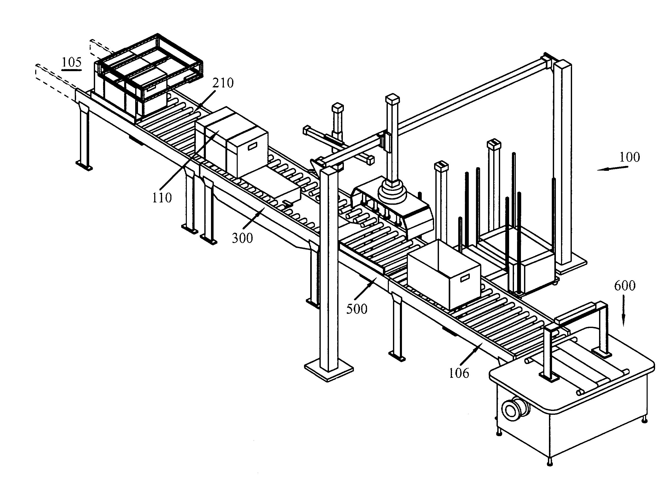
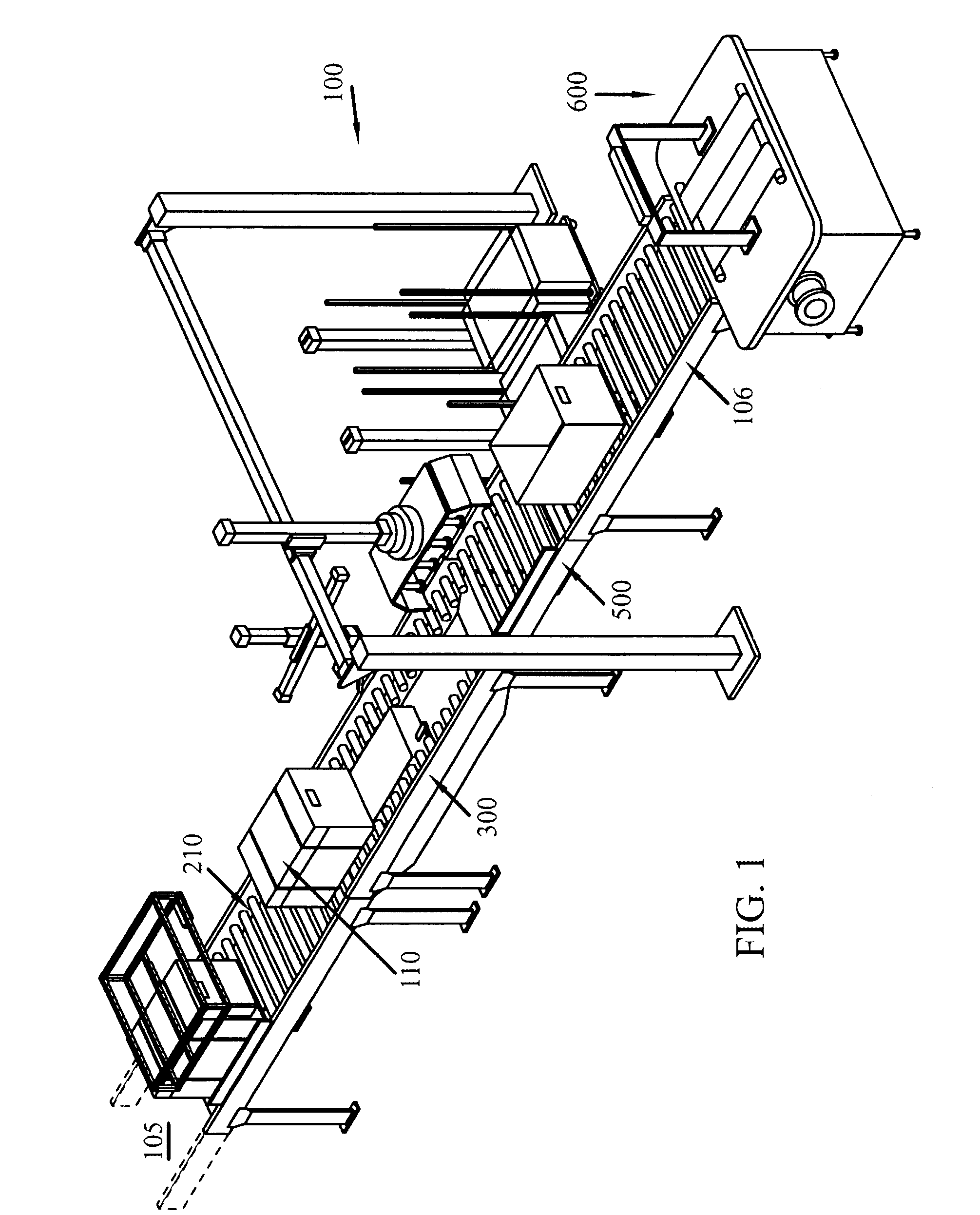
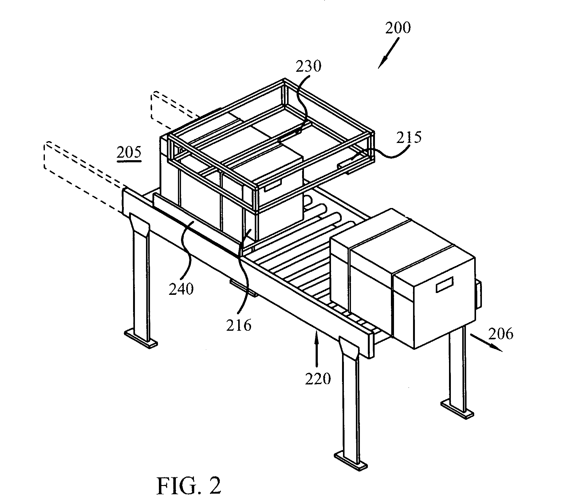
[0024]Referring initially to FIG. 1 there is shown an embodiment of the present invention comprising a lidding device 100, or Lidder / Un-Lidder system or Lidder on Un-Lidder. In one embodiment, the Lidder / Un-Lidder has a single module which incorporates all functions in a self-contained system. The single module may contain separate subsystems. Subsystem stations of lidding device 100 include tray transport / tray sizing / lid detection station 200 seen in FIG. 2 destrapping station 300, lid station 500, and tray exit / strapper 600. As shown in FIG. 1 the linear arrangement of lidding device 100 allows a workpiece to pass through the device, passing as it does, each of the subsystem stations. In an alternative arrangement the...


PUM


Abstract

A device is disclosed that can automatically remove lids from trays and place lids on trays. Further the device can sense the presence of a lid on a tray and can sense the dimensions of the tray. Based on the sensed dimensions of the tray, the device can select an appropriate sized lid to place on the tray. In one embodiment of the invention, a device holds a lid with a lid manipulator having lid holders. At least one end mechanism is attached to at least one end of the lid manipulator, and the end mechanism folds the lid flaps of an appropriate lid. Guided by the lid manipulator, lids are then positioned on the tray.

Description

CROSS-REFERENCE TO RELATED APPLICATIONS[0001]This application is a division of Ser. No. 10 / 161,155, filed on May 30, 2002, now U.S. Pat. No. 6,604,337 which claims priority from U.S. Provisional Application No. 60 / 294,000 filed on May 30, 2001, entitled “Automatic Lidder and / or Un-Lidder System and Method.” The contents of the above application is relied upon and expressly incorporated by reference as if fully set forth herein.STATEMENT REGARDING FEDERALLY SPONSORED RESEARCH OR DEVELOPMENT[0002]The invention was made by an agency of the United States government or under a contract with an agency of the United States government, the United States Postal Service (“USPS” or “Postal Service”), an independent establishment of the executive branch of the U.S. government.BACKGROUND OF THE INVENTION[0003]1. Field of the Invention[0004]The invention relates generally to handling, routing and shipping containers. More specifically, the invention relates to systems and methods for automaticall...

Claims


Application Information

Patent Timeline
Patent Type & Authority Patents(United States)
IPC IPC(8): B65B43/40B65B7/28B65B59/00B65B69/00
CPCB65B7/28B65B69/0025B65B59/00B65B43/40B65B59/003
Inventor CLOSE, DONALD R.BANKARD, MARKFINCH, WILLIAM D.CUTLIP, ROBERTLUNDAHL, ROBERT D.KOOGLE, DWIGHT
Owner US POSTAL SERVICE
Why Eureka
Try Eureka