Antitheft device for vehicle

a technology of anti-theft device and steering shaft, which is applied in the direction of anti-theft device, mechanical control device, instrument, etc., can solve the problems of long operation time for pulling out the lock bar, increased cost, and low cost, so as to reduce the burden on the drive source, the drive source can be made to be inexpensive and compact, and the effect of compact and compa

Inactive Publication Date: 2006-04-04
KK TOKAI RIKA DENKI SEISAKUSHO
View PDF9 Cites 36 Cited by
  • Summary
  • Abstract
  • Description
  • Claims
  • Application Information

AI Technical Summary

Benefits of technology

[0010]In view of the aforementioned, an object of the present invention is to provide an electrically-driven steering lock device which provides sufficient force for pulling a lock bar out, and which is compact and low-cost.
[0015]In this way, usually, the lock stopper is moved in the direction opposite the steering shaft by only the urging force of the urging device, and the locking is released. Therefore, the releasing of the locking can be carried out in a short period of time.
[0017]In such cases, the lock stopper is moved toward the side opposite the steering shaft and held by the cam which rotates interlocking with the gear due to the driving force of from the drive source. Further, at this time, the urging device also assists in moving the lock stopper. Namely, in a case in which there is resistance to the movement of the lock bar, the lock stopper is moved by both the cam and the urging device, the lock bar is pulled-out from the engagement groove of the steering shaft. Accordingly, as compared with a case in which the lock stopper is moved only by a cam, the burden on the drive source can be lessened. Therefore, the drive source can be made to be inexpensive and compact.
[0018]Further, in a state in which the lock stopper is moved toward the side opposite the steering shaft and locking is released, the lock stopper is held by both the cam and the urging device. Therefore, it is possible to reliably prevent the steering shaft from locking at unnecessary times such as while the vehicle is traveling or the like.
[0019]In this way, in the electrically-driven steering lock device of the present invention, it is possible to provide a force which is sufficient for pulling a lock bar out, and the steering lock device can be made to be compact and inexpensive. It is possible to provide an antitheft system for a vehicle and a module for a steering system which include this electrically-driven steering lock device.

Problems solved by technology

On the other hand, there are problems in that, not only does the cost increase, but also, the operation time for pulling out the lock bar is long.
When a cam mechanism is used as the driving means, the cost is lower as compared with a screw mechanism, but the efficiency of converting from rotational motion to rectilinear motion is poor, and the driving force is weak.
Therefore, problems arise in that the electrically-driving steering lock device itself becomes large and the cost thereof increases.

Method used


Image

  • Antitheft device for vehicle
  • Antitheft device for vehicle
  • Antitheft device for vehicle

Examples


Embodiment Construction

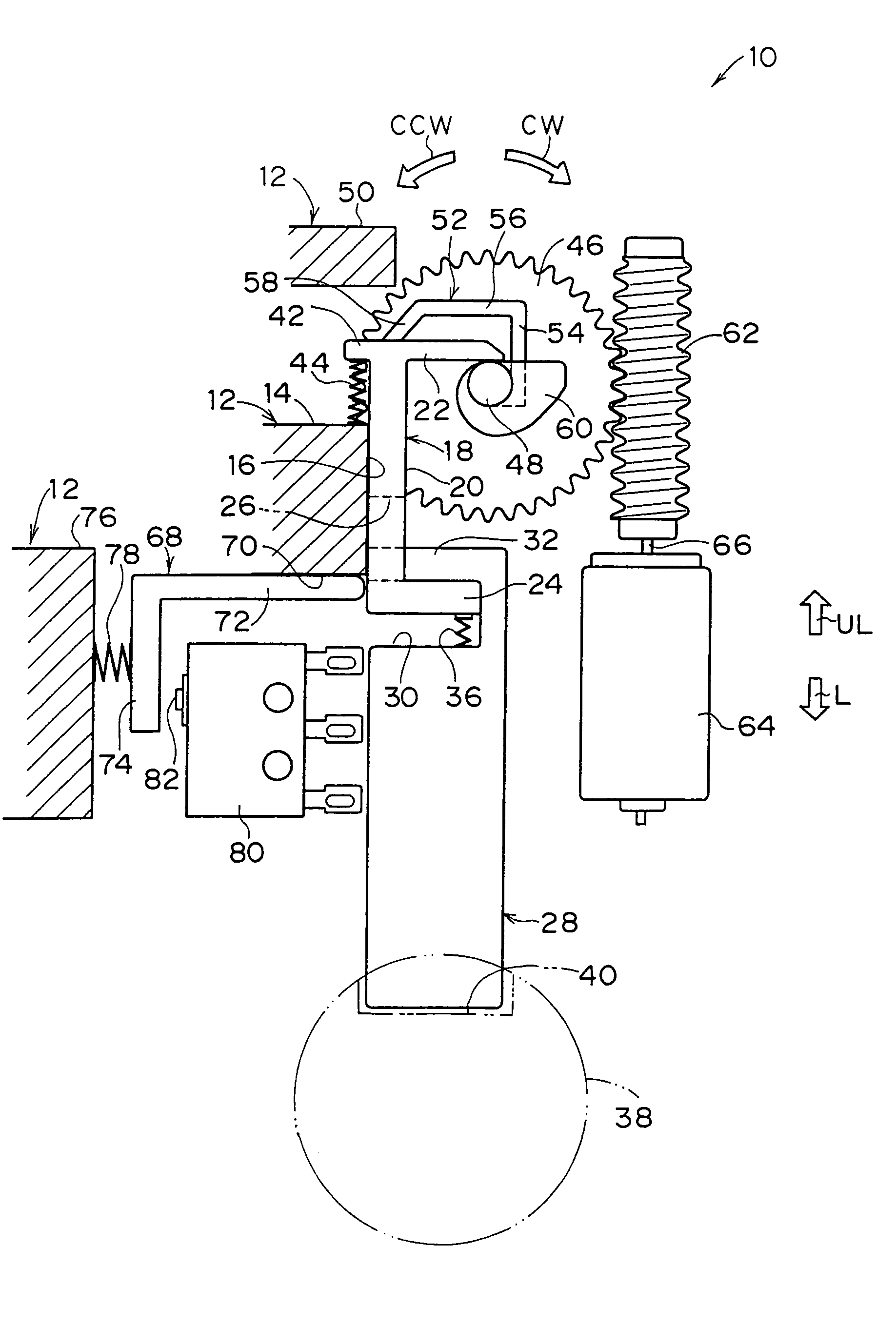
[0032]FIG. 1 illustrates, as a front view, the structure of main portions of an electrically-driven steering lock device 10 relating to an embodiment of the present invention.

[0033]The electrically-driven steering lock device 10 has a lock body 12 which is box-shaped or parallelepiped, and which is mounted to the steering post (not illustrated) of a vehicle. A block-shaped projecting portion 14 projects at the interior of the lock body 12. A lock stopper 18 is provided so as to abut a slide surface 16 of the projecting portion 14.

[0034]The lock stopper 18 has a plate-shaped slide portion 20. A plate-shaped engaging portion 22 projects, in the direction of plate thickness of the slide portion 20, at one end portion of the slide portion 20 (i.e., at the upper end portion of the slide portion 20 in FIG. 1) at the side opposite the projecting portion 14. In the same way as the engaging portion 22, a plate-shaped connecting portion 24 projects, in the direction of plate thickness of the ...


PUM


Abstract

An antitheft system for a vehicle has an electrically-driven steering lock device. In the lock device, due to a lock arm, which is formed integrally with a helical gear, being driven to rotate by a motor, a lock stopper and a lock bar are moved toward a steering shaft and are set in a locked state. Usually, locking is released by the lock stopper and the lock bar being moved toward a side opposite the steering shaft due to elastic urging force of a spring. In a case in which the lock bar catches on an engagement groove and the lock stopper cannot be moved only by the urging force of the spring, a cam, which is rotated integrally with the helical gear, pushes the lock stopper upward such that locking is released.

Description

CROSS-REFERENCE TO RELATED APPLICATION[0001]This application claims priority under 35 USC 119 from Japanese Patent Application No. 2003-24682, the disclosure of which is incorporated by reference herein.BACKGROUND OF THE INVENTION[0002]1. Field of the Invention[0003]The present invention relates to an electrically-driven steering shaft lock device which is applied to a vehicle such as an automobile.[0004]2. Description of the Related Art[0005]Vehicles such as automobiles and the like are equipped with, for example, a so-called electrically-driven steering lock device as an antitheft device. The electrically-driven steering lock device has, for example, a lock body which is assembled to the steering post of the vehicle. A lock bar, which is urged toward the steering shaft by a spring, is provided within the lock body. By making the lock bar protrude out toward the steering shaft and engage with an engagement groove formed in the steering shaft, the steering shaft is locked.[0006]A sc...

Claims


Application Information

Patent Timeline
Patent Type & Authority Patents(United States)
IPC IPC(8): B60R25/02B60R25/0215
CPCB60R25/02156B60R25/02153Y10T70/5664
Inventor FUKATSU, TOMOHIROOKUNO, MASANARISUZUKI, NORIYUKIKITO, SHOZO
Owner KK TOKAI RIKA DENKI SEISAKUSHO
Why Eureka
Try Eureka