Method and device for the measurement of exhaust gas from internal combustion engines

a technology of exhaust gas and internal combustion engine, which is applied in the direction of withdrawing sample devices, structural/machine measurement, instruments, etc., to achieve the effects of fast dynamic response, economical and technically simple solutions, and gradual adjustmen

Inactive Publication Date: 2006-04-04
PIERBURG INSTR
View PDF7 Cites 31 Cited by
  • Summary
  • Abstract
  • Description
  • Claims
  • Application Information

AI Technical Summary

Benefits of technology

[0029]For the purpose of proportional control as claimed herein, the delivery or displacement power of a device used for drawing the total volume flow is preferably adjusted correspondingly. A technically simple and therefore preferred solution is to use and adjust the rotary speed of a positive displacement pump, for example a rotary piston blower. Preferably, a Roots blower is used. As a result of this continuous proportional control, the dilution ratio is kept relatively constant, namely with regard to the smoothed curve of the exhaust gas flow. One disadvantage that might be seen when compared with the system described in U.S. Pat. No. 6,405,577 is the fact that the present invention requires a measurement of the exhaust flow, to be able to determine the averaged or smoothed curve of the exhaust flow. However, the present invention does not require measuring the exhaust volume flow or the exhaust mass flow accurately, which means that this measurement can be performed at low extra cost and effort. Finally it is possible to perform such measurement preferably before the actual test cycle, as explained in greater detail below, so that the exhaust flow no longer needs to be measured during the test cycle itself.
[0035]Because the total volume flow is adjusted proportional to a smoothed curve of the exhaust volume flow, the partial volume sampling flow from the diluted exhaust has to be regulated only slowly. The problems of a dynamic measurement of the partial sampling volume flow or total volume flow disappear. The total volume flow, for example, can easily be determined from the rotational speed of a suction device and its volume.
[0036]To be able to freely select the rotational speed and thus the delivery of the suction or exhaust device, and to be able to vary it continuously within the dynamic limits of the suction device, preference is given to the use of a Roots blower which is driven by an electric motor, which is in turn controlled by a frequency inverter. This arrangement represents an economical and technically simple solution. Theoretically it is possible to use any type of suction device for the total volume flow, with which the total volume flow can be regulated so that it corresponds to the smoothed curve of the exhaust volume flow. Because the extraction or suction device for the partial sampling volume flow also does not have to exhibit a fast dynamic response, but can slowly be readjusted, this adjustment can also be made with little technical effort or expense. In concrete implementations to measure gaseous emissions, membrane vacuum pumps were used to achieve the required gas tightness, while vane-type rotary pumps preceded by a mass flow controller were used to measure particulate emissions. Alternatively, the pumps can be adjusted without a mass flow controller. Finally, although it is not preferred according to the invention, venturis in combination with positive displacement pumps or blowers can be used both for the total flow and for the partial sampling flow, in order to control the two variables proportionally.

Problems solved by technology

One disadvantage that might be seen when compared with the system described in U.S. Pat. No. 6,405,577 is the fact that the present invention requires a measurement of the exhaust flow, to be able to determine the averaged or smoothed curve of the exhaust flow.

Method used


Image

  • Method and device for the measurement of exhaust gas from internal combustion engines
  • Method and device for the measurement of exhaust gas from internal combustion engines
  • Method and device for the measurement of exhaust gas from internal combustion engines

Examples


Embodiment Construction

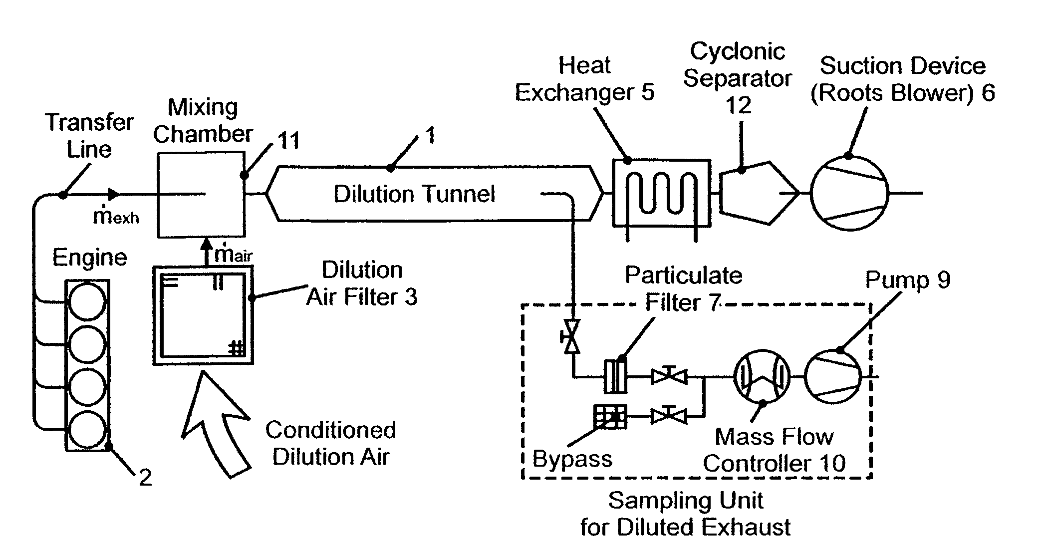
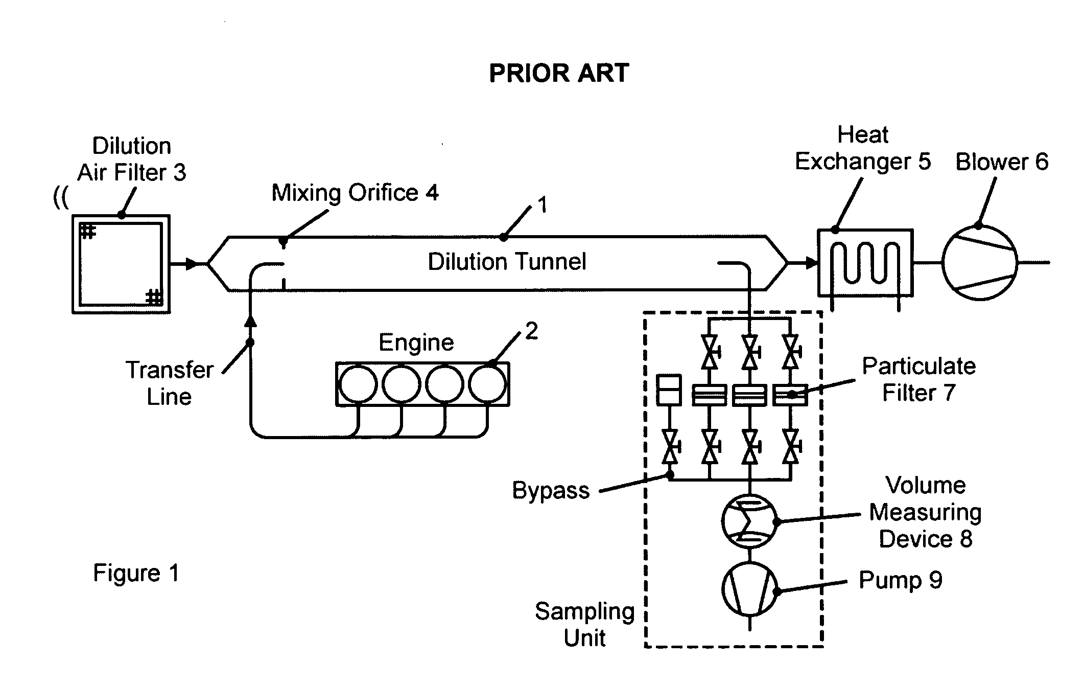
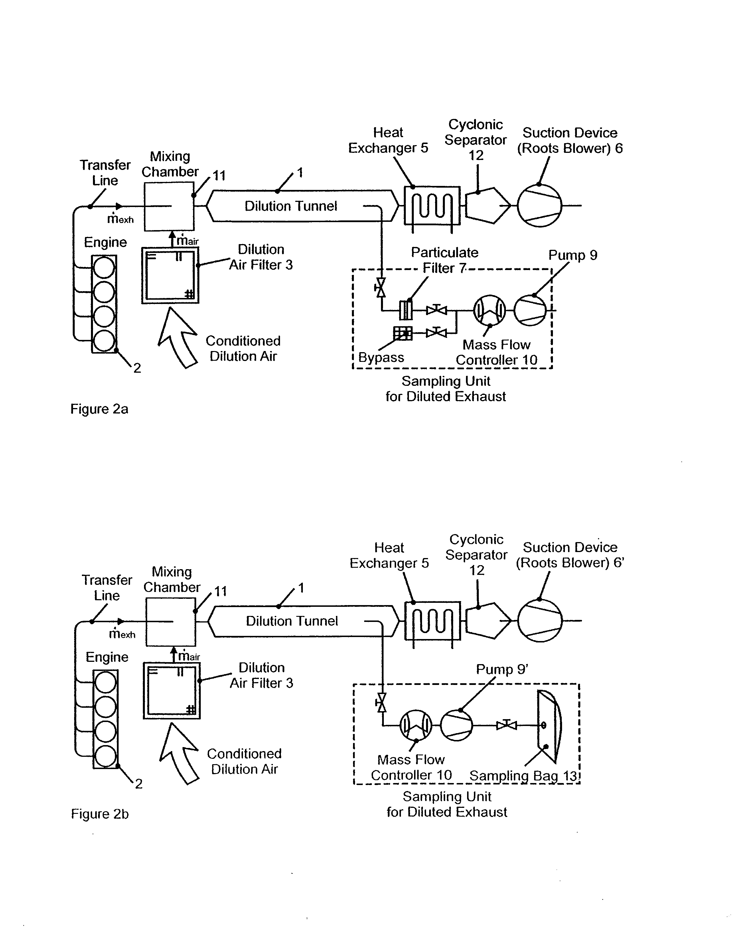
[0043]As illustrated in FIG. 2a, the exhaust from a diesel engine 2 is first conducted to a mixing chamber 11 in which it is mixed with filtered dilution air, and is then conducted to a dilution tunnel 1. At the end of the dilution tunnel, a partial sampling volume flow of the diluted exhaust-air mixture is extracted into a sampling unit and is drawn through a filter holder by means of a vane-type rotary pump 9. The filter holder can hold Teflon-coated fiberglass filters 7, for example. A mass flow controller 10 proportionally controls the partial sampling volume flow. The particulate charge of the filter 7 is measured by means of a pressure sensor (not shown).

[0044]Downstream from the dilution tunnel 1 and the extraction point for the partial sampling volume flow, the diluted exhaust-air mixture passes through a heat exchanger 5 which cools it to a defined temperature, for example to approximately 25 C., before it travels through a cyclone 12 to a Roots blower 6. The purpose of the...


PUM

PropertyMeasurementUnit
temperatureaaaaaaaaaa
massaaaaaaaaaa
Constant Volume Sampling methodaaaaaaaaaa

Abstract

A Method and device for the measurement of exhaust gas from internal combustion engines using a full-flow dilution method in which the exhaust volume flow is mixed with dilution air so that in specified test cycles, a defined total volume flow results, from which a partial sampling volume flow is extracted, on which a measurement of particulate emissions and / or gaseous components in the exhaust is conducted, and wherein a smoothed curve (II) of the exhaust flow (I) that is varied during the test cycles is determined, and the total volume flow (III) is adjusted in proportion to the variations in the measured smoothed curve of the exhaust flow.

Description

CROSS REFERENCES TO RELATED APPLICATIONS[0001]Not Applicable.STATEMENT REGARDING FEDERALLY SPONSORED RESEARCH[0002]Not Applicable.DESCRIPTION OF THE BACKGROUND ART[0003]This invention relates to a method and a device for the measurement of exhaust gas from internal combustion engines (gasoline engines and diesel engines) according to a full-flow dilution method. The full flow dilution method is often called CVS method (Constant Volume Sampling method) because the current regulations require a CVS method which is a full flow dilution method with constant volume sampling. The method and device of the invention are suitable both for a gravimetric measurement of particulates in the exhaust gas, as well as, for a measurement of gaseous exhaust components in the emissions.[0004]Laws and regulations in Europe and in the United States of America limit the emission of gaseous and solid / liquid pollutant components in the exhaust of gasoline and diesel engines. According to current regulations...

Claims


Application Information

Patent Timeline
Patent Type & Authority Patents(United States)
IPC IPC(8): G01M19/00G01M15/04G01M99/00G01N1/22G01N33/00
CPCG01N1/2252G01N33/0018G01N2001/2264
Inventor SCHMIDT, ROLAND
Owner PIERBURG INSTR
Why Eureka
Try Eureka