Hot dairy-based beverage dispenser

a beverage dispenser and hot technology, applied in the field of hot dairy-based beverage dispensers, can solve the problems of not being used in the dispensation of hot dairy-based beverages, the atmosphere pressure collapses the bag, etc., and achieves the effects of reducing or eliminating many of the problems associated, great consistency, and constant flow ra

Inactive Publication Date: 2006-04-04
ECKENHAUSEN ROLAND B +1
View PDF18 Cites 74 Cited by
  • Summary
  • Abstract
  • Description
  • Claims
  • Application Information

AI Technical Summary

Benefits of technology

[0010]It is an object of the present invention to provide a fresh dairy-based hot beverage dispensing system that greatly reduces or eliminates many of the problems associated with conventional systems. One primary feature of the present invention is to provide a system that employs a self-contained unit in which a refrigerated milk supply is located in a cabinet above the emulsification unit. This allows milk to descend from the refrigeration unit at least partially under the force of gravity. Thus, the amount of milk supplied varies less due to fluctuations in the strength of suction from the venturi orifice. Rather, there is a highly constant flow rate of milk dispensed with great consistency each and every time the unit is actuated.
[0015]A further feature of the present invention is an automated time and / or dispensing interval related, self-cleaning system for flushing out all components that are exposed to milk flow. This is accomplished by positioning a flush control valve and a three-way valve, acting as a diversion valve, in the air supply line that leads to the air inlet of the emulsification unit. After each dispensation of a quantity of milk through the emulsification unit, the flush control valve and the pump are actuated and the diversion valve is positioned such that it allows a flow of flushing water through the air supply line, and through the emulsification chamber, to rinse out any residual milk that may have seeped into the air supply line, and also to rinse out the emulsification chamber itself. The only other connection to the emulsification chamber is from the steam boiler, which discharges steam with each actuation. A small quantity of steam may also be vented through the emulsification chamber following the dispensation of each portion of a dairy-based beverage. Consequently, all the components of the emulsification system that are in contact with the dairy-based liquids can be flushed or purged following each use of the machine for dispensing a dairy-based beverage. By providing this self-cleaning feature, the system of the invention avoids the chore of requiring cleaning of the unit between beverage dispense cycles and throughout the normal daily course of business.
[0016]A further feature of the present invention is the minimization of nondisposable components that are exposed to the flow of milk. The emulsification chamber and its milk inlet and nozzle seating inlet cavities are supplied as one disposable unit that is discarded each day following use. The nozzles themselves are reusable, but are very easy to clean. Thus, the beverage dispenser of the present invention to a very large extent eliminates the cleaning requirement that is required with conventional units of this type.
[0018]In addition to the fact that the invention comprises software that enables a constant supply of steam at multiple target temperatures, the software also enables the boiler system to maintain these multiple, different, programmable temperatures within a very narrow bandwidth of +2° C. or −2° C. This is accomplished by means of an algorithm. The software keeps track not only of the actual steam temperature inside the boiler, but also of the rate at which the steam temperature increases or decreases while heating up or cooling down. This allows the software to anticipate when a programmed target temperature will be reached. The quantification of this anticipation is used to turn the heating element(s) inside the steam boiler on or off in advance of reaching the target temperature. The result is that the fluctuations of the actual temperature around the target temperatures are reduced significantly. The temperature inside the boiler is maintained within a narrow bandwidth which results in the supply of steam at stable temperatures.
[0024]The dairy liquid flow control valve is used in two positions, 1) the OFF (no activation of the magnetic coil) position which completely blocks the flow of the dairy-based liquids from the chilled storage container to the venturi-based emulsifier, and 2) the ON position (activation of the magnetic coil). The ON position allows for an uninterrupted gravitational flow of the dairy-based liquids from the chilled storage container to the venturi-based emulsifier. As previously indicated, this aspect of the invention is particularly useful with “bag in box” milk storage containers.
[0027]An aspect of some embodiments of the invention may be considered to be an improvement in a device for emulsifying dairy-based beverages with selected other fluids, including air, and dispensing an emulsified mixture of selected fluids including a dairy-based beverage from an emulsifier. According to the improvement of this aspect of the invention, a source of air above atmospheric pressure is connected to the emulsifier. The system therefore does not rely solely upon suction created by the venturi effect of the emulsifier to supply air for the beverage mix. The use of pressurized air may improve the consistency of the temperature and the proportions of fluids in the beverage mixture as the beverage is discharged from the emulsifying unit.

Problems solved by technology

As the milk supply in the bag is used up, atmospheric pressure collapses the bag.
While “bag in box” milk containers have been utilized for many years in the dispensation of cold milk, they have not heretofore been employed in the dispensation of hot dairy-based beverages.

Method used


Image

  • Hot dairy-based beverage dispenser
  • Hot dairy-based beverage dispenser
  • Hot dairy-based beverage dispenser

Examples


Embodiment Construction

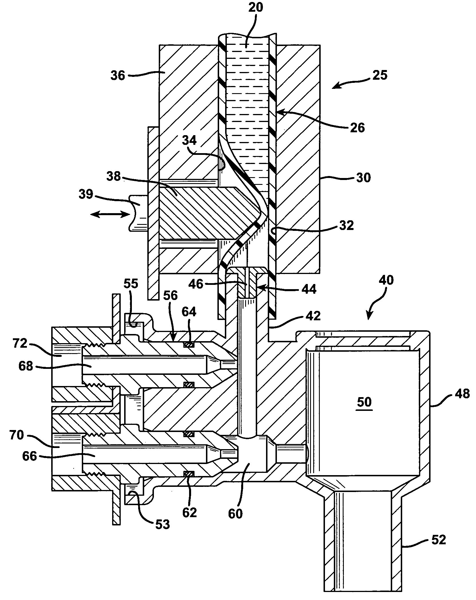
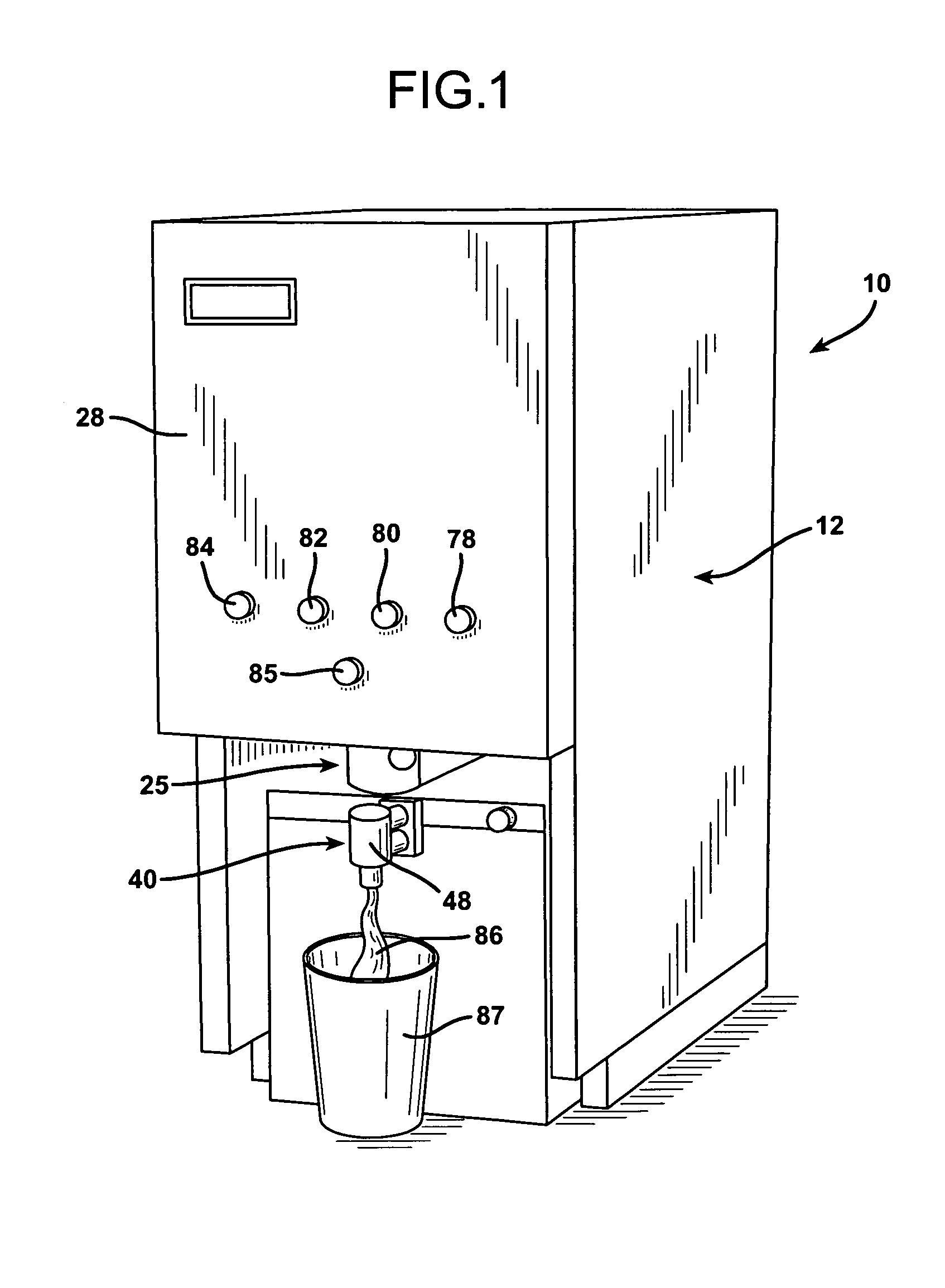
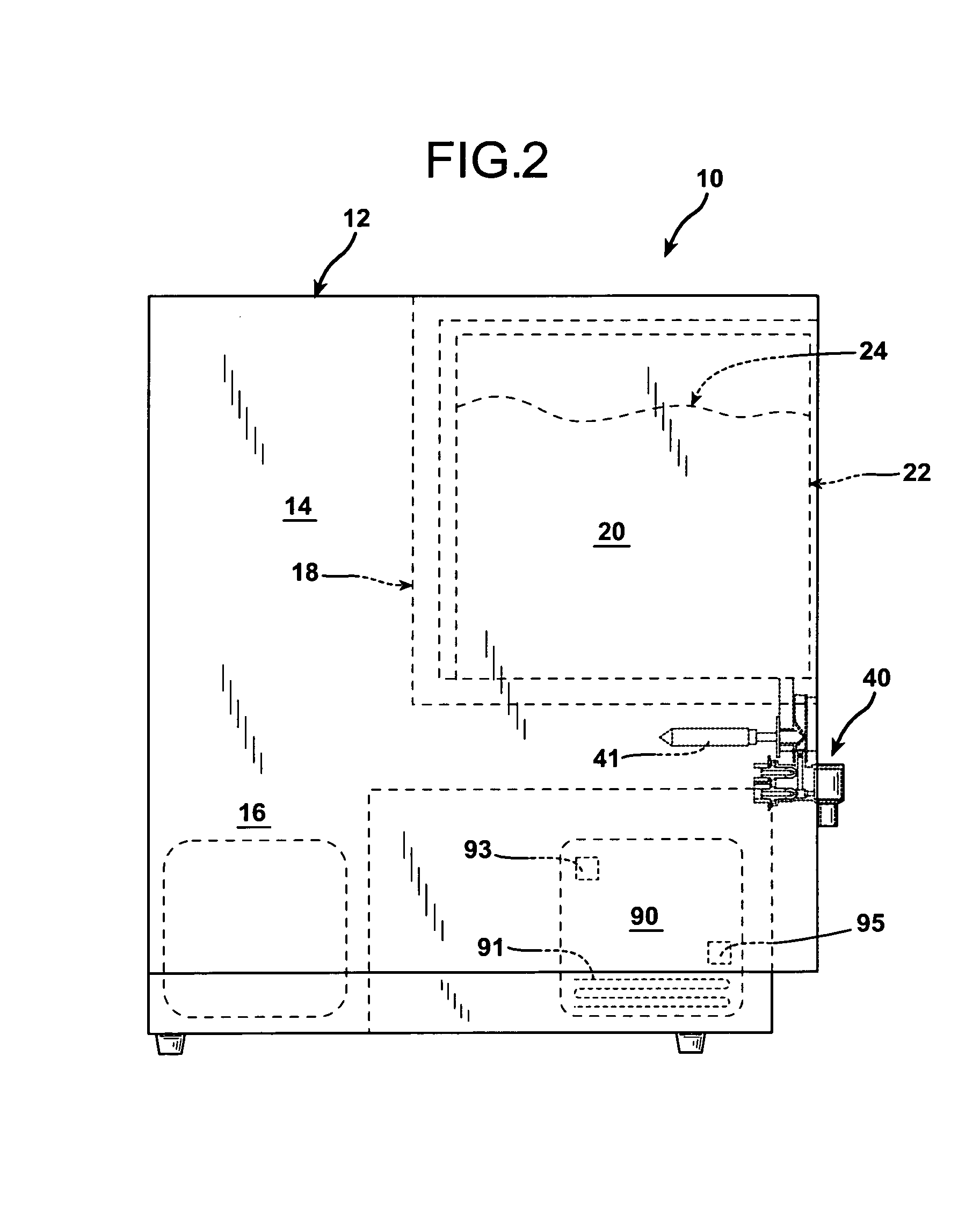
[0035]FIG. 1 illustrates an emulsification and dispensing device 10 that employs a cabinet 12 having an upper portion indicated generally at 14 in FIG. 2, and a lower portion indicated generally at 16 in that drawing figure. The upper portion 14 includes an electrically operated refrigerator 18 having cooling coils that keep the cooling cavity thereof at a temperature of preferably between about 32° F. and 40° F. The cooling cavity of the refrigerator 18 can accommodate a disposable “bag in box” milk container 22, or any other containing device such as a regular / standard one gallon or one-half gallon plastic container or carton that holds a supply of milk 20 in the upper portion 14 of the cabinet 12. Specifically, the container 22 is formed of a corrugated paperboard outer, rectangular box within which a flexible, collapsible plastic bag 24 is located. The bag 24 is equipped with a discharge hose 26, best illustrated in FIG. 3, which is formed of a short length of rubber tubing. The...


PUM

PropertyMeasurementUnit
pressureaaaaaaaaaa
temperatureaaaaaaaaaa

Abstract

A dispensing unit for dispensing hot, dairy-based beverages has a self-contained refrigerated unit located above a venturi-type emulsification foaming head. The dispensing unit has particular applicability to the dispensation of foamy, hot milk for use in beverages such as cappuccino and nonfoamy, hot milk for use in beverages such as coffee latte, hot chocolate, and other hot dairy-based beverages. The refrigeration unit accommodates a “bag in box” cold milk storage container of the type widely used in food service establishments. The dispensing unit employs a pinch valve that avoids direct contact between the milk and the valve components. The refrigerated milk is stored above the level of the foamer head so that the flow of milk results partially from gravitational force on the milk, and is not totally dependent upon venturi suction created in the foamer head.

Description

BACKGROUND OF THE INVENTION[0001]1. Field of the Invention[0002]The present invention relates to an improved system for emulsifying milk or other dairy-based liquids with other fluids and dispensing them for ultimate consumption in a hot beverage. The invention has particular applicability in the preparation of hot dairy-based beverages such as hot chocolate, cappuccino, coffee latte, flavored steamers (heated flavored milk), and other hot beverages containing dairy-based liquids.[0003]2. Description of the Prior Art[0004]Various systems have existed for quite a number of years for emulsifying dairy-based liquids, such as milk, with other fluids in the preparation of hot beverages. For example, U.S. Pat. No. 4,715,274 describes an emulsifier unit for emulsifying steam, air, and milk to prepare such beverages as cappuccino and coffee latte. In the preparation of such beverages steam and air are mixed with milk or cream in a venturi-type emulsification chamber and dispensed from this ...

Claims


Application Information

Patent Timeline
Patent Type & Authority Patents(United States)
IPC IPC(8): A01J11/00B67D1/04A47J31/44B67D1/08B67D1/12B67D3/00B67D3/04G07F13/00
CPCA47J31/4485A47J31/461A47J31/469G07F13/00
Inventor ECKENHAUSEN, ROLAND B.ECKENHAUSEN, STEVEN C.
Owner ECKENHAUSEN ROLAND B
Why Eureka
Try Eureka