
Connecting rod and crankshaft assembly for an engine

a technology of connecting rods and crankshafts, applied in the direction of connecting rods, shafts and bearings, etc., can solve the problems of increasing the overall number of components and the likelihood of mechanical failure, increasing manufacturing and maintenance costs, and overly complex design of connecting rods, so as to achieve the effect of maximizing the effective length of connecting rods

Inactive Publication Date: 2006-04-04
STANCZYK DAN
View PDF10 Cites 15 Cited by
  • Summary
  • Abstract
  • Description
  • Claims
  • Application Information

AI Technical Summary

Benefits of technology

[0008]The engine assembly of the present invention is generally provided with a block having at least one cylinder, a crankshaft rotatably coupled with said block, a piston slidably disposed within the cylinder, and a connecting rod that couples the piston to the crankshaft. The connecting rod is provided with an elongated body portion that extends between opposite ends. The body of the connecting rod has at least one bend along its length so that a portion of the centerline of the body is angularly and laterally spaced from an axis that extends through the opposite ends of the connecting rod. In a preferred embodiment, the crankshaft is rotatably coupled with the block so that the centerline of said crankshaft is horizontally spaced from a bore centerline of the cylinder. The displaced position of the crankshaft works in concert with the bend in the connecting rod to maximize the effective length of the connecting rod and produce a maximum compression just past top dead center.
[0009]It is therefore a principal object of the present invention to provide an engine having angular or curved connecting rods that maximize the power and efficiency of the engine by maximizing the effective length of the connecting rod.
[0010]A further object of the present invention is to provide an engine that combines curved or angular connecting rods with a crankshaft that is displaced from a centerline of the engine's piston bore to maximize the effective length of the connecting rods.
[0012]Yet another object of the present invention is to provide an engine having increased overall efficiency and reduced overall size.
[0013]A further object of the present invention is to provide an engine having an increased overall efficiency that is simple in design.
[0014]Still another object of the present invention is to provide an engine having an increased overall efficiency with relatively low manufacturing and maintenance costs.

Problems solved by technology

This design provides an improved level of engine efficiency but increases the overall number of component parts and the likelihood of mechanical failure.
Moreover, the complex geometry and multiple pivot points of the compound linkage create increased manufacturing and maintenance costs.
However, much like the compound connecting rods, this connecting rod design is overly complex, suffering from manufacturing and maintenance costs that outweigh the benefits gained in power and efficiency.

Method used


Image

  • Connecting rod and crankshaft assembly for an engine
  • Connecting rod and crankshaft assembly for an engine
  • Connecting rod and crankshaft assembly for an engine

Examples


Embodiment Construction

[0022]In the following detailed description of exemplary embodiments, reference is made to accompanying FIGS. 1–6, which form a part hereof and show, by way of illustration, exemplary embodiments of the present invention. These embodiments are disclosed in sufficient detail to enable those skilled in the art to practice the invention. It is to be understood that other embodiments may be utilized, however, and other changes may be made without departing from the spirit or scope of the present invention. The following detailed description is, therefore, not to be taken in a limiting sense in that the scope of the present invention is defined only by the appended claims.

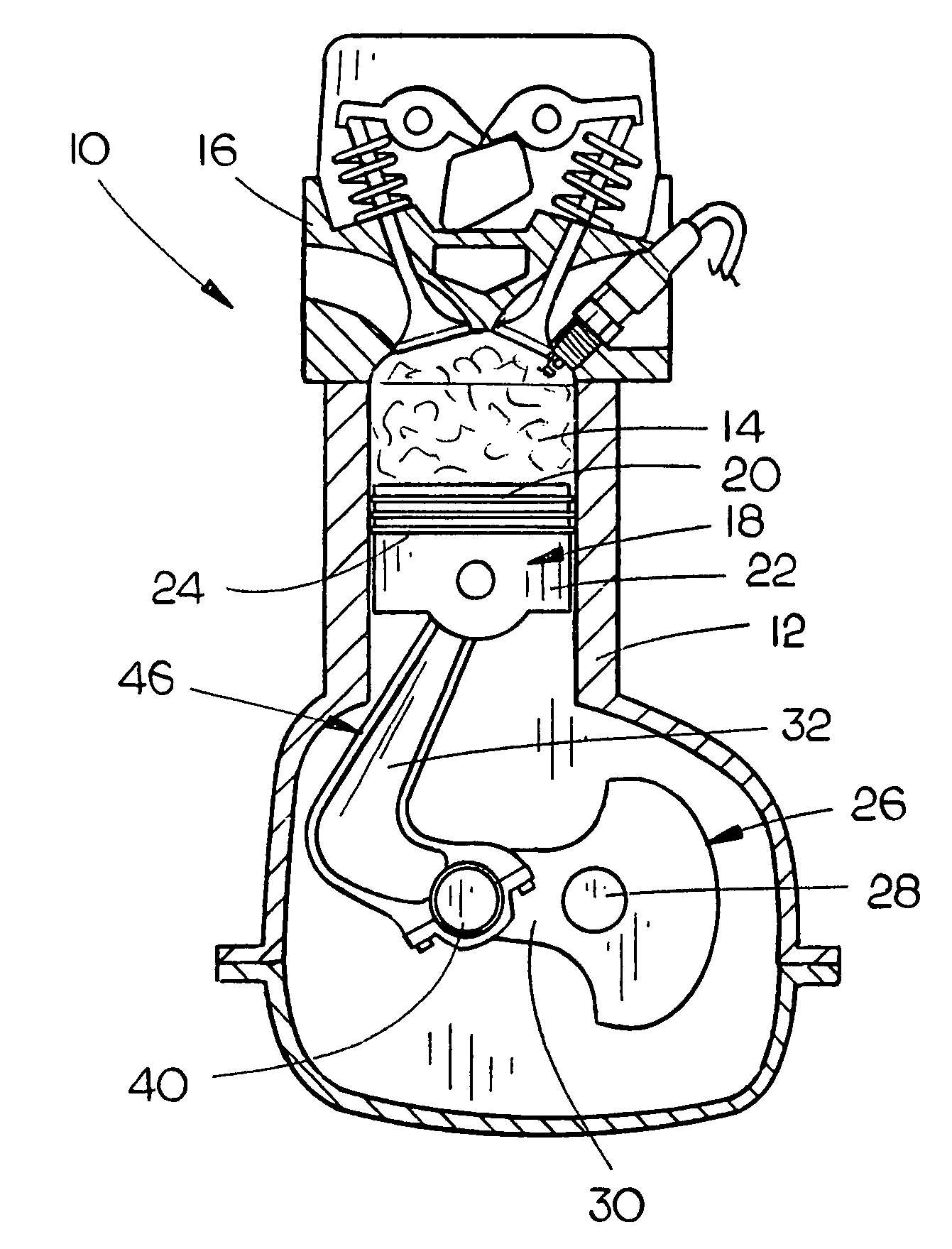
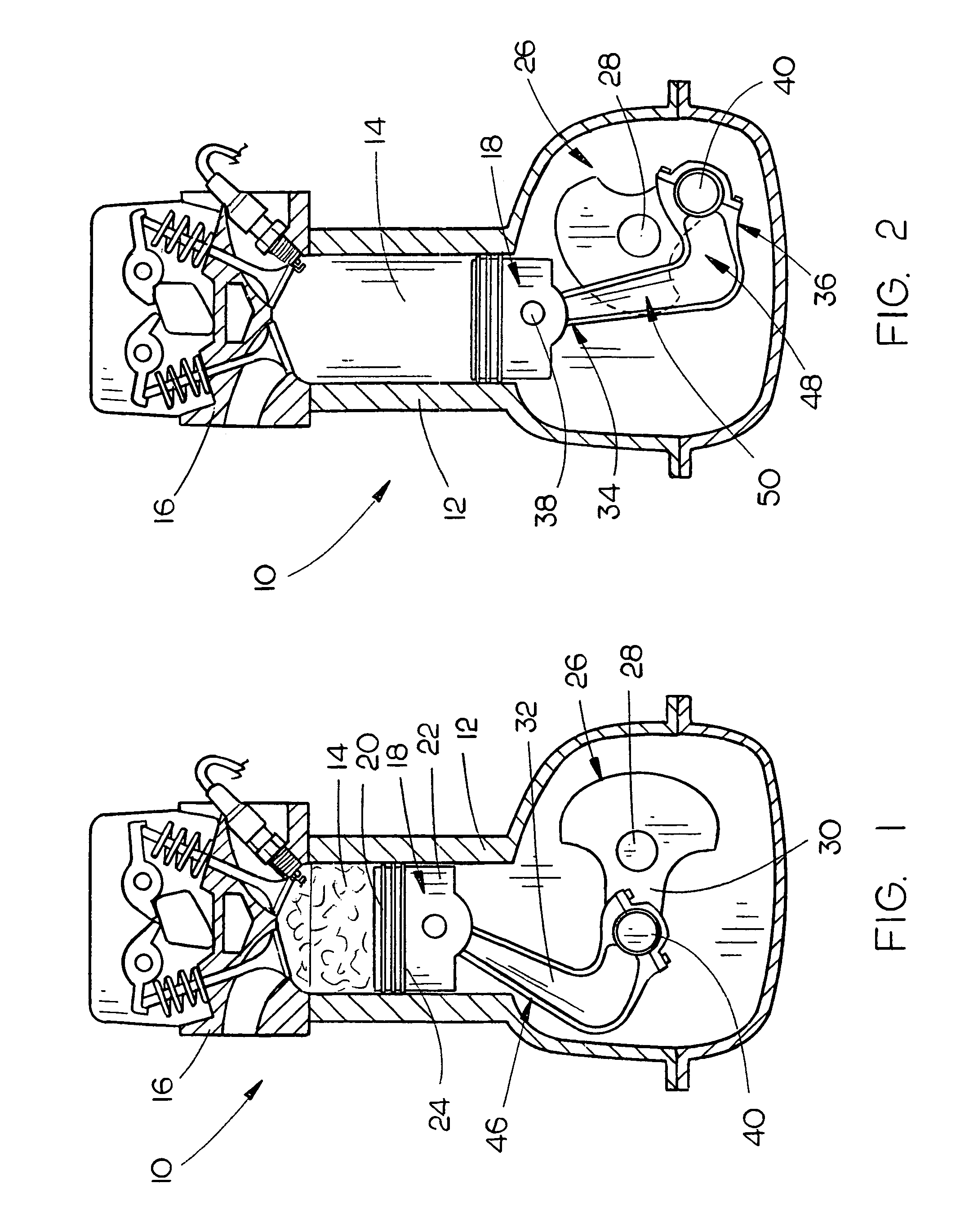
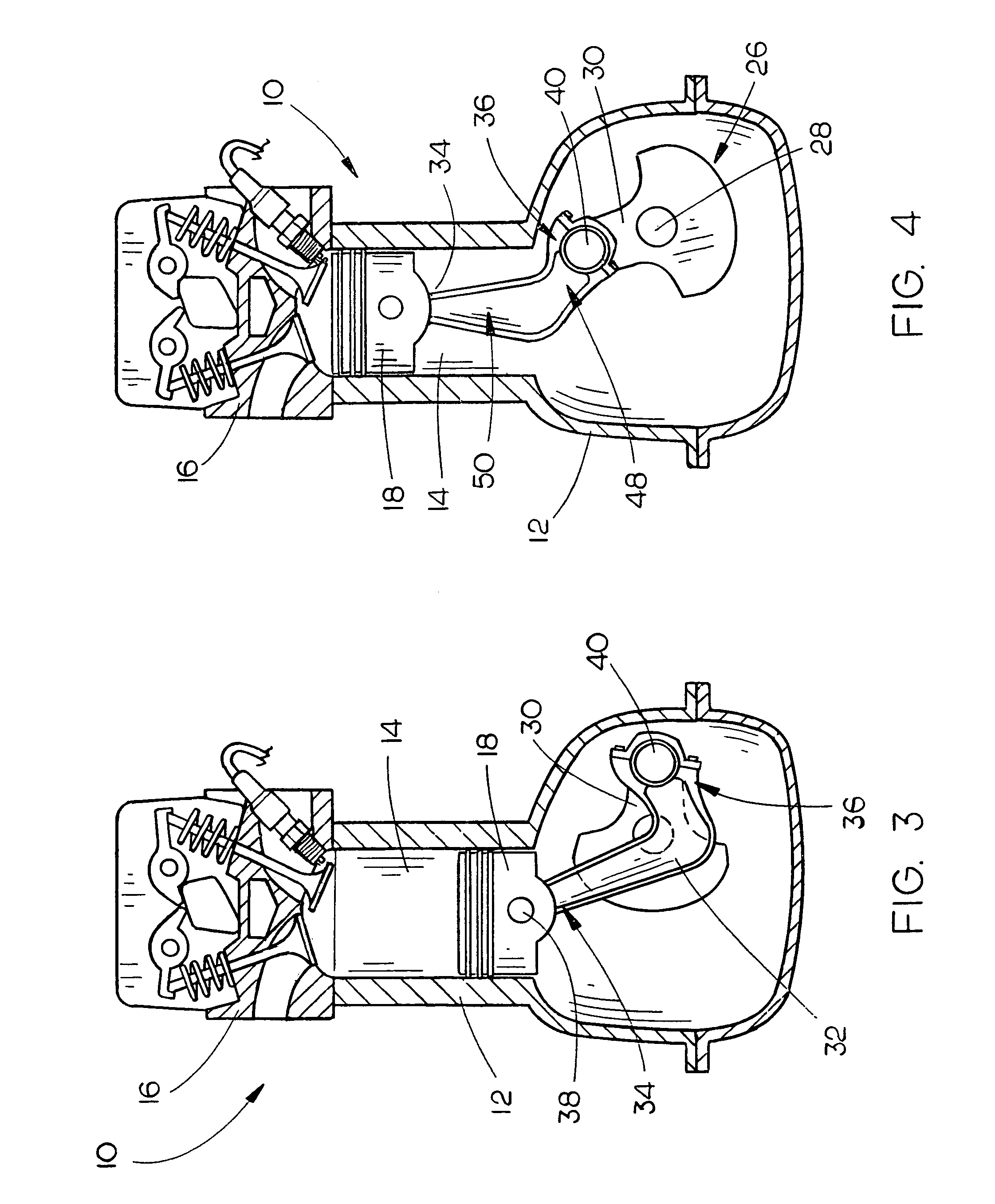
[0023]The engine 10 of the present invention is generally provided with a block 12 having at least one cylinder 14, which is defined by interior walls of the block 12 and a cylinder head 16. For ease of explanation only, the engine 10 will be described as having a single cylinder. However, it is contemplated that the pr...


PUM


Abstract

A novel engine is provided with a crankshaft that is offset from a centerline of the bore shaft, where a reciprocally sliding piston is disposed. A curved or angularly shaped connecting rod is pivotably connected to the piston at one end and to the crankshaft at the opposite end. The position of the crankshaft and the shape of the connecting rod maximize the travel of the connecting rod through the piston stroke in relation to the overall size of the connecting rod. The design permits maximum compression to be achieved after the top dead center of the crankshaft to further promote engine efficiency.

Description

BACKGROUND OF THE INVENTION[0001]1. Field of the Invention[0002]The present invention relates to engines and more particularly to an engine having at least one curved or angular connecting rod that couples at least one piston to a crankshaft, which is offset from a centerline that extends through the piston bore.[0003]2. Description of the Prior Art[0004]Engines of having various designs and configurations power automobiles, lawn mowers, generators, compressors, and more. Most internal combustion engines are comprised of similar components, which typically include a block, a crankshaft, a piston and a connecting rod that couples the piston with the crankshaft. The connecting rod is crucial in that it transfers the reciprocating power of the piston to the rotating crankshaft. The most common connecting rod design is straight, rotatably connected at one end to a wrist pin in the piston and at the other end to a crankpin on the crankshaft. Many prior art engine designs have attempted t...

Claims


Application Information

Patent Timeline
Patent Type & Authority Patents(United States)
IPC IPC(8): F02B75/32
CPCF02B75/32F16C7/023F02F7/0019Y10T74/2162
Inventor STANCZYK, DAN
Owner STANCZYK DAN
Learn More