Proportional pressure assist ventilation controlled by a diaphragm electromyographic signal

a technology of electromyographic signal and diaphragm, which is applied in the direction of valve operating means/releasing devices, diagnostic recording/measuring, and identification of people. it can solve the problems of inability to evaluate respiratory drive by measuring such as the rate of pressure rise or lung volume, and none of these parameters can provide reliable measures

Inactive Publication Date: 2006-04-04
UNIV DE MONTREAL
View PDF37 Cites 47 Cited by
  • Summary
  • Abstract
  • Description
  • Claims
  • Application Information

AI Technical Summary

Benefits of technology

[0013]Another object of the present invention is to provide a closed-loop system responsive to the intensity of the diaphragm EMG measured immediately before the onset of inspiratory flow to quantify pre-inspiratory breathing effort in view of automatically or manually adjusting a level of extrinsic positive end expiratory pressure (PEEP) applied to a patient in proportion to changes in EMG intensity of pre-inspiratory efforts. In this manner, the pre-ventilatory intensity of the diaphragm EMG can be maintained at a desired, minimum level such that the pre-inspiratory neural drive remains stable at a desired target minimal level. Determination of the duration from the onset of EMG to the onset of respiratory flow is also used for quantitative evaluation of the intrinsic PEEP, and to guide adjustment of the trigger sensitivity of the ventilator systems.

Problems solved by technology

However, none of these parameters can provide a reliable measure of the respiratory neural drive because they are affected by changes in neuro-mechanical or neuro-ventilatory efficiency.
Evaluation of respiratory drive by measurements such as the rate of rise in pressure or lung volume is not reliable when, for example, the muscle length or the respiratory system impedance are affected by changes in the neuro-ventilatory efficiency.

Method used


Image

  • Proportional pressure assist ventilation controlled by a diaphragm electromyographic signal
  • Proportional pressure assist ventilation controlled by a diaphragm electromyographic signal
  • Proportional pressure assist ventilation controlled by a diaphragm electromyographic signal

Examples


Embodiment Construction

[0031]Although the preferred embodiment of the present invention will be described in relation to a double subtracted EMGdi signal, it should be kept in mind that the concept of the present invention can be used with any respiratory muscle signal.

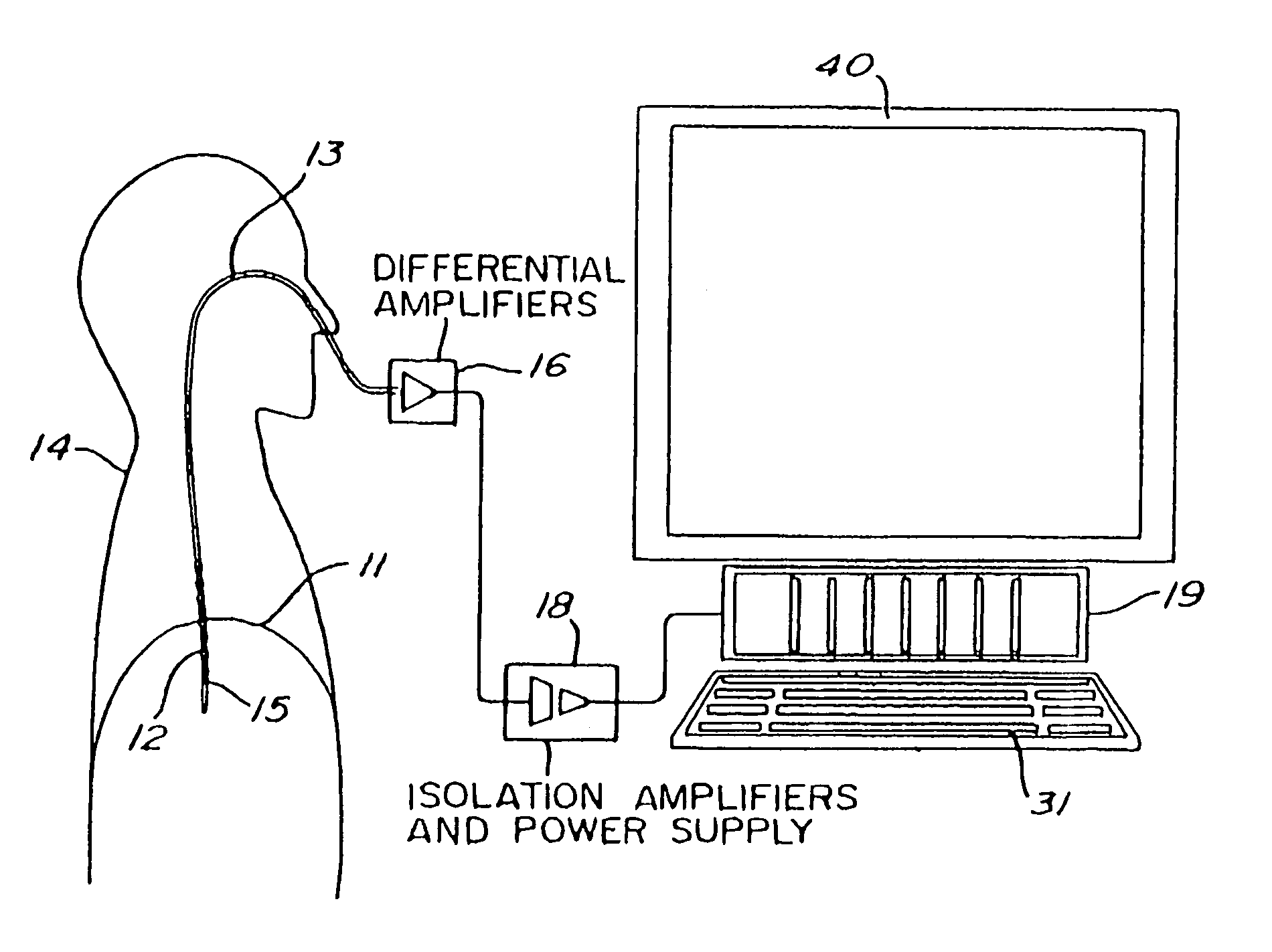
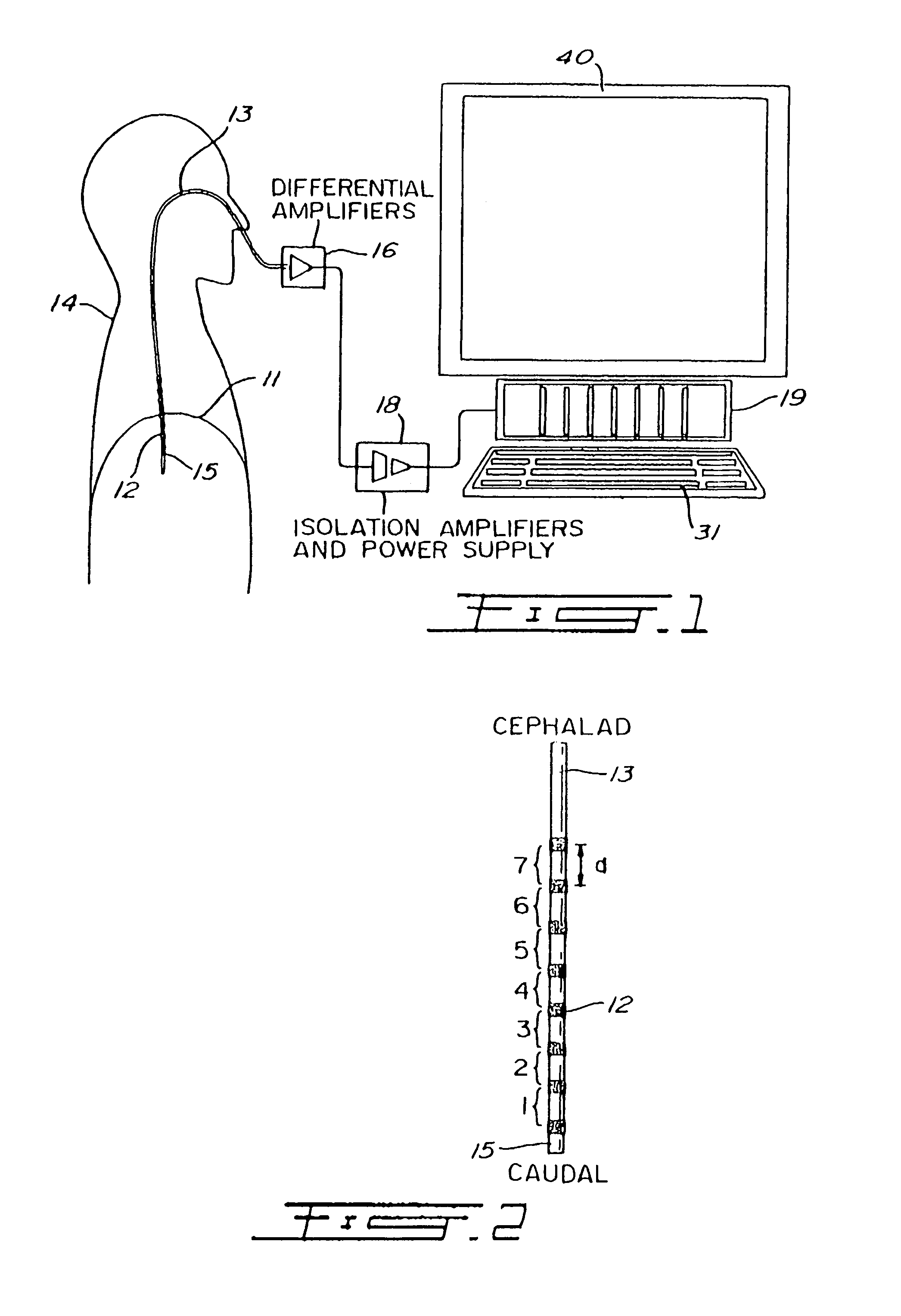
[0032]To measure EMG activity of the diaphragm 11 (EMGdi) of a human patient 14, an array of electrodes such as 12 (FIGS. 1 and 2) are mounted on the free end section 15 of an oesophageal catheter 13, with a constant inter-electrode distance d (FIG. 2). As shown in FIG. 1, the catheter 13 is introduced into the patient's oesophagus through one nostril or the mouth until the array of electrodes 12 is situated at the level of the gastroesophageal junction. The diaphragm 11 and / or the oesophagus slightly move during breathing of the patient 14 whereby the array of electrodes 12 also slightly moves about the diaphragm 11. As will be explained in the following description, autorhatic compensation for this displacement is provided for.

[0033]Accor...


PUM


Abstract

A closed loop system uses (a) the intensity of the diaphragm electromyogram (EMG) for a given inspiratory volume; (b) the inspiratory volume for a given EMG intensity; or (c) a combination of (a) and (b); in view of controlling the level of gas flow, gas volume or gas pressure delivered by a mechanical (lung) ventilator. The closed loop ventilator system enables for automatic or manual adjustment of the level of inspiratory support in proportion to changes in the neuro-ventilatory efficiency such that the neural drive remains stable at a desired target level. An alarm can also be used to detect changes in neuroventilatory efficiency in view of performing manual adjustments.

Description

BACKGROUND OF THE INVENTION[0001]1. Field of the Invention[0002]The present invention relates to a system using the intensity of the diaphragm electromyogram (EMG) at a given lung volume or the lung volume at a given EMG intensity to automatically or manually adjust the level of inspiratory support in proportion to changes in the neuro-ventilatory efficiency.[0003]The present invention also relates to a system responsive to the intensity of the diaphragm electromyogram (EMG) measured immediately before the onset of inspiratory flow to automatically or manually control and maintain an optimum level of extrinsic positive end expiratory pressure (PEEP) applied to a patient, and to automatically or manually control a duration from the onset of EMG to onset of respiratory flow.[0004]2. Brief Description of the Prior Art[0005]Prior art algorithms used to create closed-loop ventilator systems are based on variables such as tidal volume, respiratory rate, inspiratory flow, end-tidal carbon ...

Claims


Application Information

Patent Timeline
Patent Type & Authority Patents(United States)
IPC IPC(8): A61M16/00A62B7/00F16K31/02A61B5/296
CPCA61B5/0492A61M16/00A61M16/0051Y10S128/925A61M2230/08A61M2230/60A61M2210/1014A61M16/026A61B5/296
Inventor SINDERBY, CHRISTERBECK, JENNIFER
Owner UNIV DE MONTREAL
Why Eureka
Try Eureka