Plate for a sliding cooler grate

a cooler grate and sliding technology, applied in the direction of handling discharged materials, combustion processes, lighting and heating apparatus, etc., can solve the problems of arching or warping, rubbing on the topside, and the front edge sinking a littl

Inactive Publication Date: 2006-04-04
CLAUDIUS PETERS TECH
View PDF12 Cites 8 Cited by
  • Summary
  • Abstract
  • Description
  • Claims
  • Application Information

AI Technical Summary

Benefits of technology

[0011]According to the invention, the front region of the cover plate can rest freely on the support part, there being no positive connection between the front region of the cover plate and the support part. However, if there is a risk that the cover plate could warp or, in the case of specific thermal states, could lift off on the end face from the support part in an undesirable way, holding means which prevent such lifting-off, without impeding the expansion of the cover plate in the direction of its surface extent, can be provided.
[0012]Since the invention makes it possible to exchange the cover plate in the event of wear, it is also appropriate to provide an exchangeable wearing part for that region of the grate plate which is at the greatest risk of wear, namely its end face.

Problems solved by technology

They therefore expand to a greater extent on the topside than on the underside, this leading to arching or warping, as a result of which their front edge sinks a little.
This may cause it to rub on the topside of the next following plate.
This disadvantage can be avoided by providing, by virtue of construction, appropriately large vertical play between successive plates, although this is undesirable because it causes more material to fall through in the region of overlap on the plates.

Method used


Image

  • Plate for a sliding cooler grate
  • Plate for a sliding cooler grate
  • Plate for a sliding cooler grate

Examples


Embodiment Construction

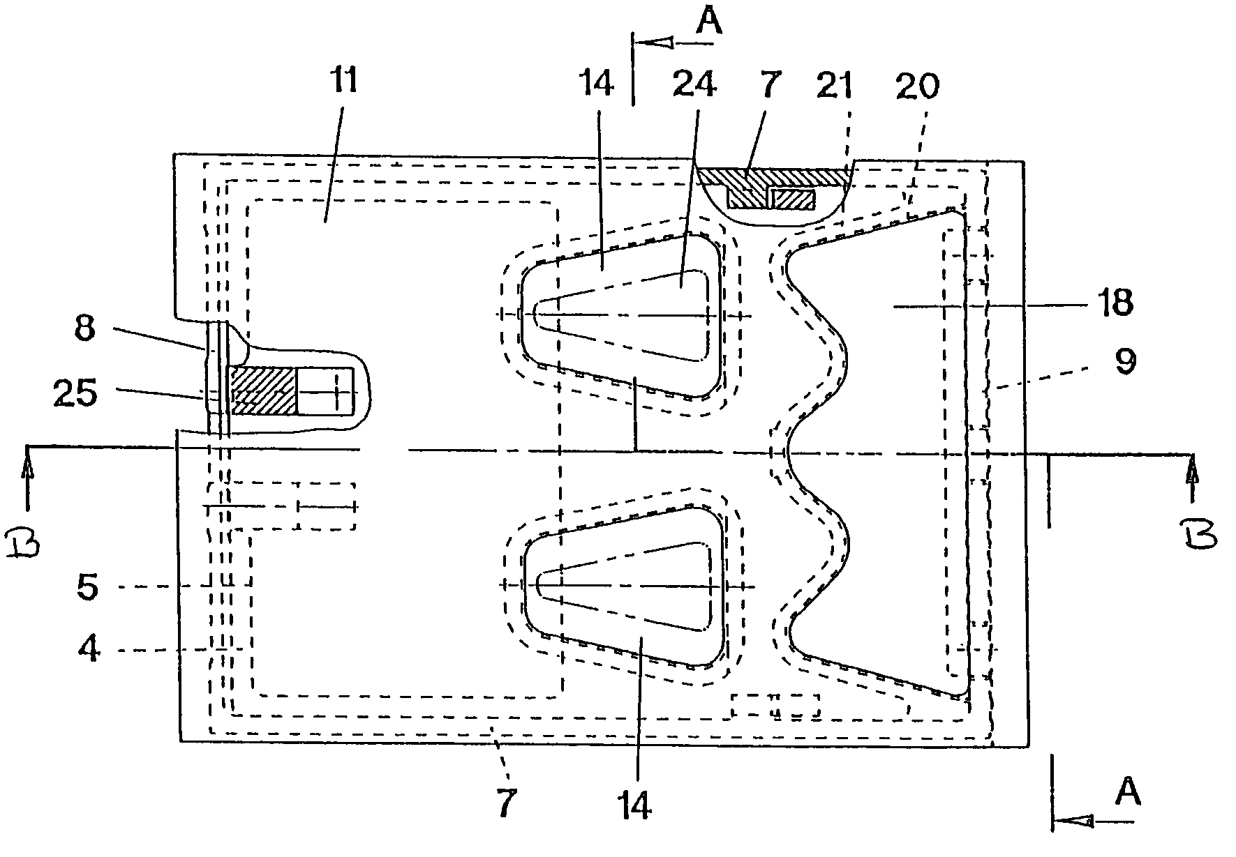
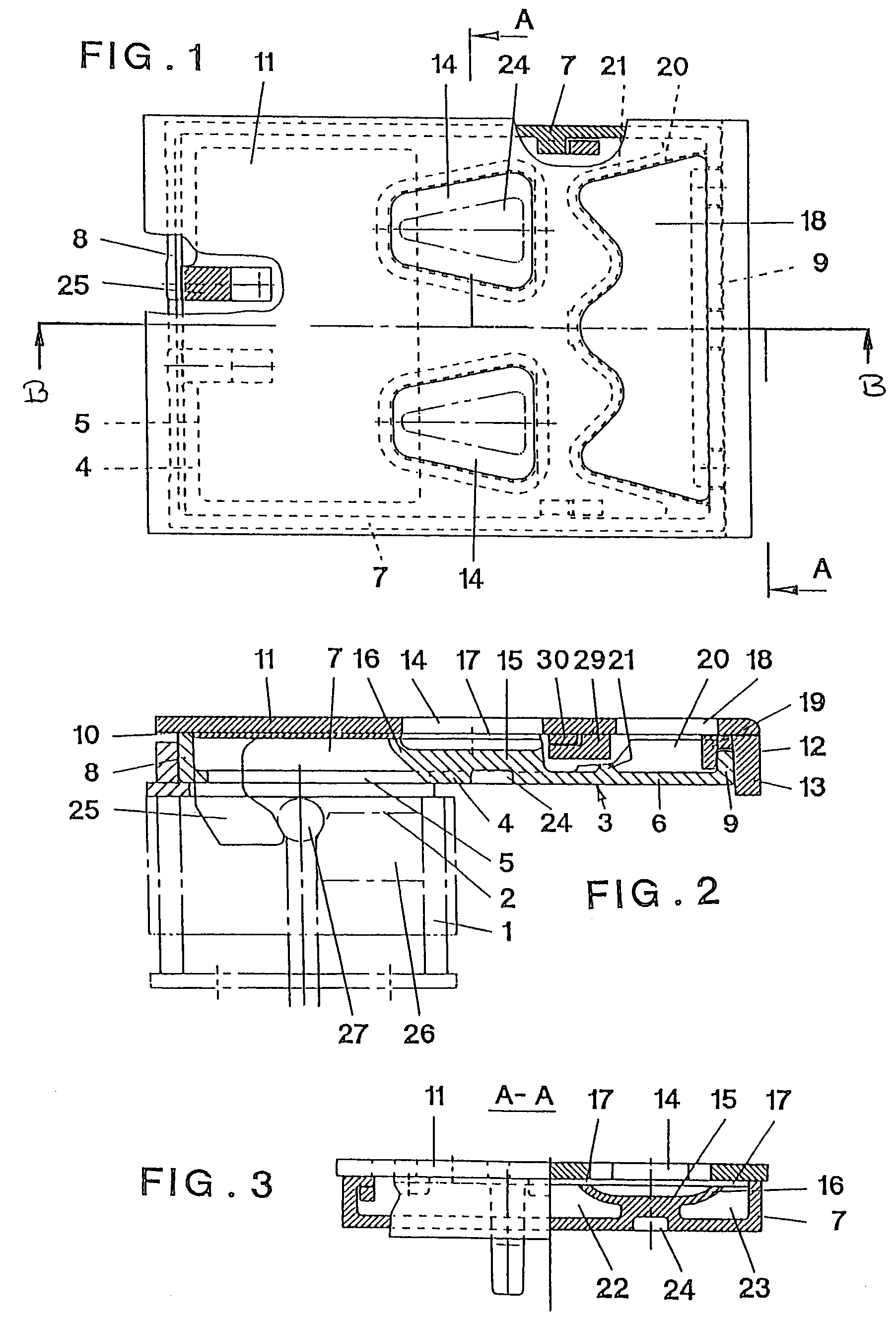
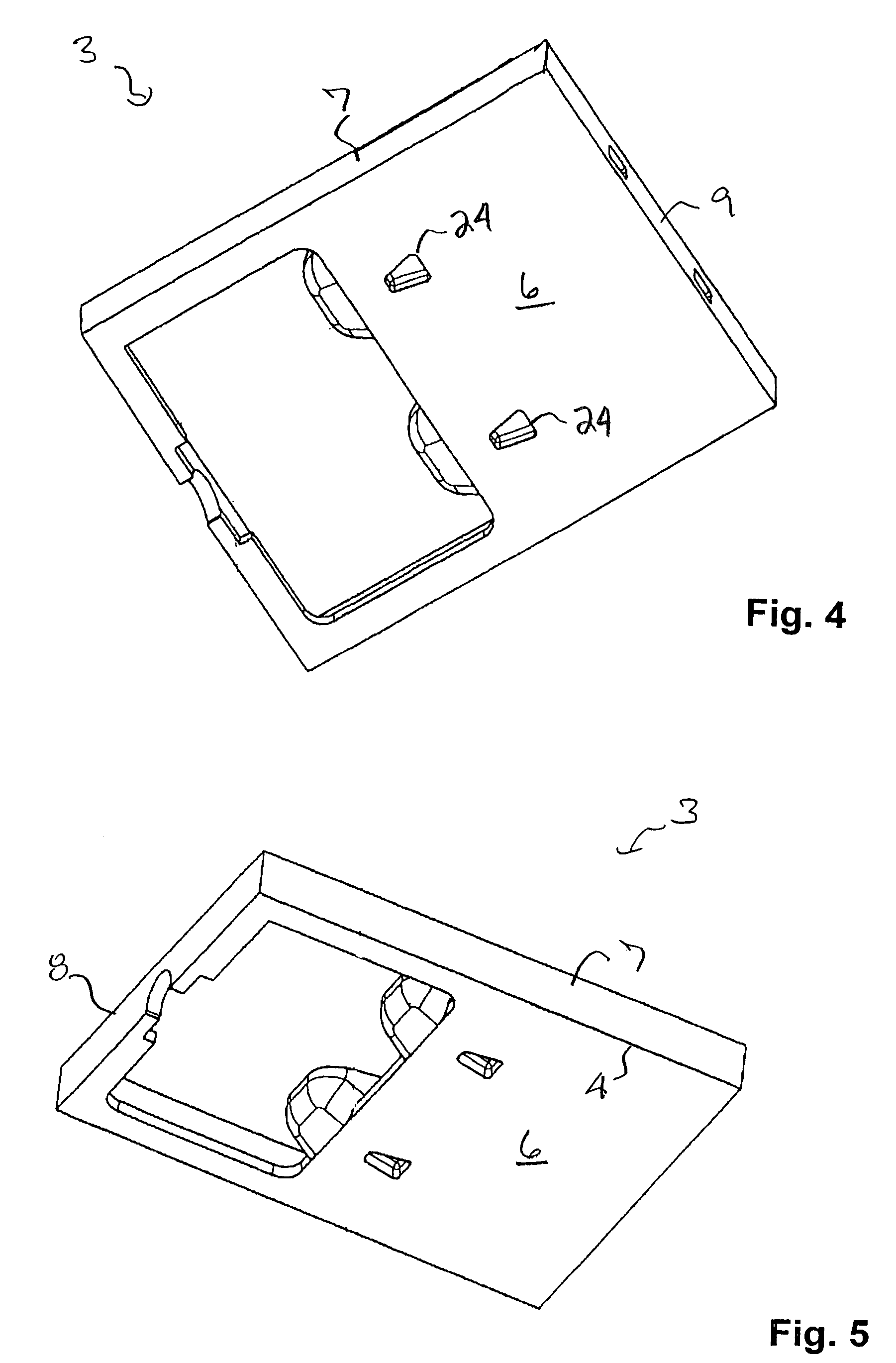
[0023]A multiplicity of plates, of which only one appears in the drawing, are arranged next to one another on the grate-plate carrier 1 which is formed continuously over the grate width by one or more hollow profiles. The topside of the grate-plate carrier 1 is cut out in the region of each grate plate to form a cooling-air supply orifice 2. It is surrounded by a top edge, on which the grate plate sits. For this purpose, there is provided on the underside of the support part 3 a correspondingly designed peripheral edge 4 which sits sealingly on the edge of the grate-plate carrier and which encloses the plate-side cooling-air supply orifice 5. The edge 4 has adjoining it forwards in one piece a bottom 6 which extends essentially parallel to the plane of the edge 4. From the edge 4 and the bottom 6 rises a peripheral frame of lateral edge strips 7, of a rear edge strip 8 and of a front edge strip 9 which form an upper bearing surface 10 which is essentially parallel to the topside of ...


PUM

PropertyMeasurementUnit
thicknessaaaaaaaaaa
cross-sectional sizeaaaaaaaaaa
bending stressaaaaaaaaaa

Abstract

Grate plate for the push-type grate of a clinker cooler, which has a topside bearing surface exposed to the hot material to be cooled. The grate plate including a rear region having devices for connection to a grate-plate carrier, such that the grate plate front projects over an adjacent grate plate. Longitudinally extending edge strips are connected in a force-transmitting manner to the devices for connection to the grate-plate carrier to support the plate front. The topside bearing surface is formed by a cover plate which is free of the edge strips, at least in front of the grate-plate carrier, and which has freedom of expansion in the horizontal direction in relation to the support part comprising the edge strips.

Description

CROSS-REFERENCE TO RELATED APPLICATIONS[0001]This is the national stage of International Application No. PCT / EP95 / 04370, filed Nov. 6, 1995 and which designated the United States.BACKGROUND OF THE INVENTION[0002]Push-type grates for coolers for cement clinker and suchlike pourable combustible material are known, these push-type grates being formed by grate-plate rows which extend transversely relative to the longitudinal direction of the grate and to the conveying direction of the material and which are alternately stationary and moved back and forth in the conveying direction. The individual grate plates of each row have a topside which forms the bearing surface for the bed of material to be cooled. They are carried by a grate-plate carrier, to which they are connected in the rear region of their underside via corresponding connection devices. They project forwards from the grate-plate carrier, in order to overlap the rear part of the grate plates of the next following grate-plate ...

Claims


Application Information

Patent Timeline
Patent Type & Authority Patents(United States)
IPC IPC(8): F23K3/08F23H7/02C04B7/47F27D15/02
CPCF27D15/022
Inventor FEHSENMAYR, THEOFRUHLING, REINERHEINRICH, FRANKMEYER, HARTMUT
Owner CLAUDIUS PETERS TECH
Why Eureka
Try Eureka