Induction heating work coil

a technology of work coils and induction heating, which is applied in the direction of coil arrangements, electric heating, electric/magnetic/electromagnetic heating, etc., can solve the problems of increasing the unit and inventory cost of the unit, affecting the operation and efficiency of the flat work coil being used, and reducing the total efficiency of the induction profiler

Inactive Publication Date: 2006-04-04
COMAINTEL
View PDF11 Cites 18 Cited by
  • Summary
  • Abstract
  • Description
  • Claims
  • Application Information

AI Technical Summary

Benefits of technology

[0012]An induction heating device for heating electroconductive material to a desired temperature. The device has an open core of magnetic material shaped in a U. The device also has a coil of electrically conductive material wound separately on each leg of the U, each of the legs becoming the pole pieces of a magnetic flux concentrator whenever an excitation current is passed through the two coils in parallel to produce a variable magnetic field of very high flux density in the space between the two edges, facing each other, at the ends of the two poles, and closest to the material being heated thereby allowing the induction heating device to accommodate a change in diameter of an apparatus to be heated by the induction heating device without a change in the core and the coils. In the device each of the coils are wound around each leg in a direction such that on excitation, when one leg becomes the N pole of the flux concentrator the other leg becomes the S pole of the concentrator, the legs alternating in polarity when the excitation current alternates in polarity, thereby forcing the magnetic flux to pass between the edges at the ends of the pole pieces, facing each other, and through the material to be heated.

Problems solved by technology

Once an induction profiler has been installed on the equipment being heated, changes in roll diameters invariably result in a decrease in induction profiler total efficiency or in cases where the processes requires changes to a roll of different diameter, the replacement of the workcoil for one matching the new roll diameter.
Roll and cylinder diameters vary over a very wide range, requiring a similar wide range of work coils, increasing their unit and inventory costs.
As a result of maintenance grinding for roll resurfacing as well as expansion during heating, the diameter of a given roll changes and this affects the operation and efficiency of the flat work coil being used to heat the roll.
Further flat coils were not that efficient.
Since the flat coil was fairly large, it was difficult to use in some locations.
Thus the coil of the '086 patent has the problems discussed above for flat coils.

Method used


Image

  • Induction heating work coil
  • Induction heating work coil
  • Induction heating work coil

Examples


Embodiment Construction

)

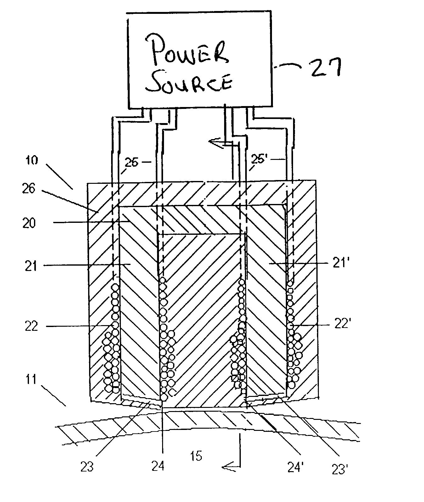
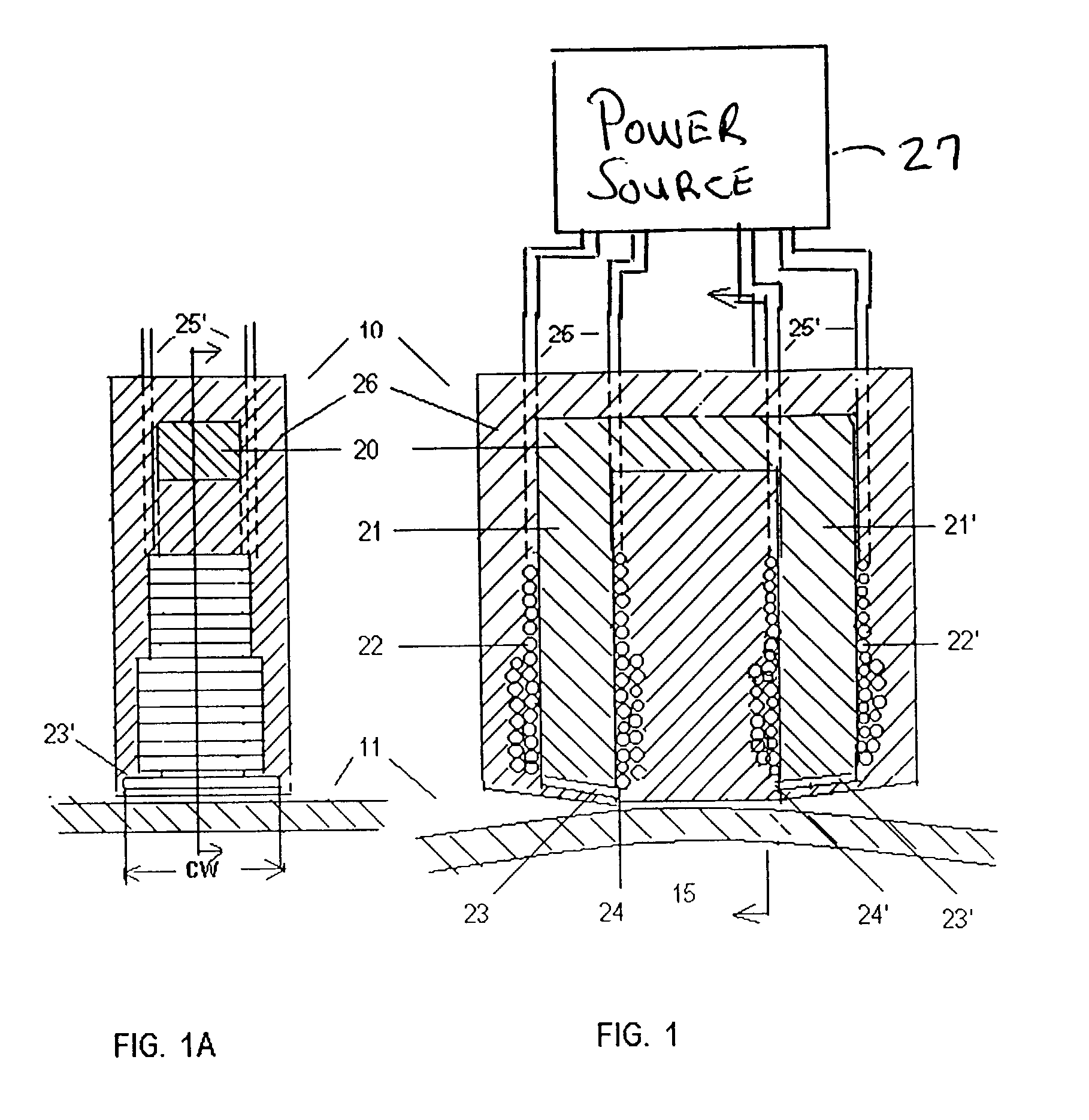
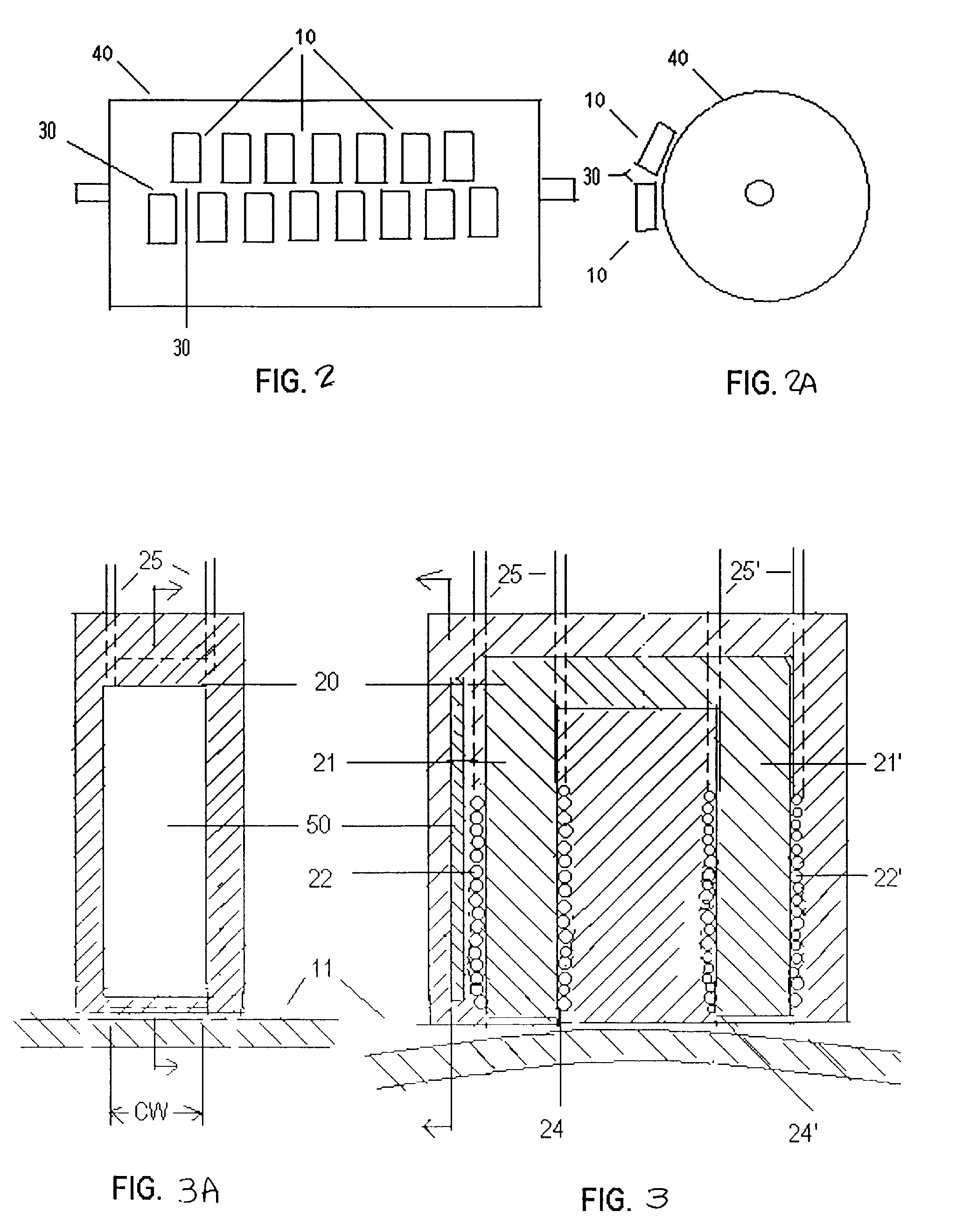
[0019]Referring now to FIG. 1 there is shown a cross-sectional view of an induction heating device or work coil 10 embodied in accordance with the present invention. Work coil 10 is closely spaced to the surface 11 of a roll 15 whose ferromagnetic surface, is to be heated by the work coil. The work coil comprises an open core 20 of ferrite material shaped in a U defining opposed legs 21 and 21′ about each of which a coil 22 and 22′ of Litz wire is wound. As is shown in FIG. 1, the wire is wound partially single and double layered around each leg. Thus the legs 21 and 21′ now become the pole pieces 21 and 21′ of a magnetic flux concentrator whenever an excitation current is passed through the two coils 22 and 22′ (in parallel) to produce a variable magnetic field.

[0020]How and where the coil 22 and 22′ is wound around each leg 21 and 21′ is very important for maximum efficiency of the work coil of the present invention. In winding each coil 22 and 22′ around each leg 21 and 21′, the...


PUM


Abstract

An induction heating device or work coil for heating electroconductive material to a desired temperature that can be used on a roll or cylinder of any diameter. The work coil has an open core of ferrite material shaped in a U. Wire is wound around the opposing legs of the U so that on excitation one leg becomes the N pole and the other leg becomes the S pole and the polarity alternates as the polarity of the excitation current alternates. A substantially thin rectangular flat layer of ferrite can be attached to ends of each pole piece. Each layer of ferrite has having a length sufficient to cover bottom end of each leg and a width in the direction of an axis perpendicular to the face of the U that corresponds to the width of the desired control heating effect.

Description

FIELD OF THE INVENTION[0001]This invention relates to induction heating devices or work coils for heating electroconductive material to a desired temperature and more particularly to such a coil that can be used on a roll or cylinder of any diameter.DESCRIPTION OF THE PRIOR ART[0002]Papermaking and many other industrial processes presently use or would benefit from using induction heating to raise the surface temperature or to control the local diameter of steel and cast iron rolls. Examples of these industrial processes include (1) methods for controlling a nip and a desired physical property of a product involving a web material subjected to a roll pressing operation; (2) methods for heating a rotating roll surface uniformly; (3) methods for pressing and drying a web on rotating metal cylinders; (4) methods of calendering web material; (5) laminating and (6) operations such as: glazing; soldering; bonding or welding; hot metal pressing, extruding, etc. The typical induction profil...

Claims


Application Information

Patent Timeline
Patent Type & Authority Patents(United States)
IPC IPC(8): H05B6/14
CPCH05B6/145
Inventor LARIVE, RENELARIVE, SYLVAIN
Owner COMAINTEL
Why Eureka
Try Eureka